


Transformer Core Engineering Notes · CF-N211
An oil gap and a pressboard barrier are not interchangeable units of insulation. The liquid provides electrical insulation and heat transport; the solid barrier shapes the insulation arrangement and can separate liquid regions. Their combined performance depends on geometry, material properties and condition. Replacing one with more of the other is a design change, not a simple thickness conversion.
Specify what the barrier is doing
A barrier may divide a liquid space, provide a defined surface path or maintain a mechanical separation. These functions are not identical. Show its position, edges, overlap and support in the insulation drawing. A material certificate can identify the pressboard grade, but does not establish that a particular barrier arrangement is adequate. Review the complete path between energized and grounded parts, including regions near leads, end rings and clamps.
Material properties affect field sharing
In a simplified series dielectric arrangement under capacitive conditions, the materials’ permittivities influence how voltage is shared. Actual transformer geometry also includes non-uniform fields and surface effects. Weidmann discusses matching insulation material properties to the surrounding liquid as one design consideration. This does not mean that a lower-density board is always preferable: mechanical support, processing behaviour and the approved insulation system still need to be satisfied by the selected grade.
Keep the cooling path visible
A larger barrier or additional sheet can restrict liquid movement or alter the available duct. Conversely, enlarging a liquid gap changes the winding envelope and may affect support. Compare the thermal and dielectric drawings together before accepting either change. Confirm the dimensions after impregnation and compression where relevant. An insulation improvement claimed from a nominal section can be misleading if the final assembly closes a flow path or moves an adjacent conductor.
Ask for arrangement-specific evidence
The review package should identify the liquid, pressboard grade, material condition and relevant AC or impulse duty. Link the selected dimensions to the OEM’s verification basis. Do not derive universal minimum gaps from a short public standard abstract or an unrelated test object. Where the supplier relies on an established design, document which dimensions and materials must remain unchanged for that evidence to apply. Manufacturing acceptance should verify those controlling features.
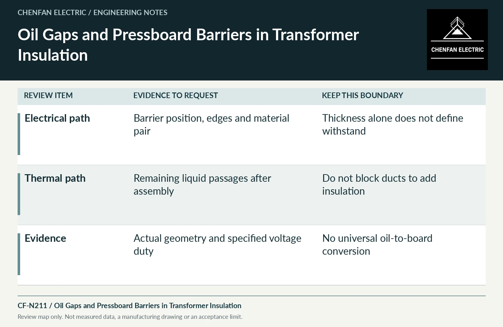
| Review item | Evidence to request | Boundary to preserve |
|---|---|---|
| Electrical path | Barrier position, edges and material pair | Thickness alone does not define withstand |
| Thermal path | Remaining liquid passages after assembly | Do not block ducts to add insulation |
| Evidence | Actual geometry and specified voltage duty | No universal oil-to-board conversion |
References and scope
- IEC 60076-3:2013+AMD1:2018 CSV — Insulation levels and dielectric testsPublic standard abstract · Insulation levels, dielectric testing and external clearances; the article does not reproduce test values or design distances.
- Optimizing transformer insulation systemsManufacturer technical page · Interaction of solid insulation, spacers, flow and mechanical support.
- IEC 60076-2:2011 — Temperature rise for liquid-immersed transformersPublic standard abstract · Temperature-rise requirements, cooling identification and the distinction between test conditions and installed duty.