

Long tap leads need separate support assessments for transport inertia and fault electromagnetic forces. Compare event-specific directions, durations and displacement on the manufactured insulation geometry. A linear dynamic response needs its mass, frequency and damping, rather than just a static peak load [1].
Calculation basis. Project-specific values and gates in the illustrative screens below are assumptions; cited catalogue values retain their source test conditions.
Start with the free spans between effective restraints. A clip that locates the lead during assembly may have little stiffness in the direction of interest. Conversely, a rigid attachment can transfer a concentrated moment into the paper insulation or support board.
Define the excitation before choosing the load
For transport, retain the shipping orientation, attached masses and applicable acceleration or vibration history. Include the connection to the active part: treating the support feet as fixed can omit movement of the structure carrying them. For a fault, use the relevant current combinations, return conductors and leakage field to determine distributed force and direction.
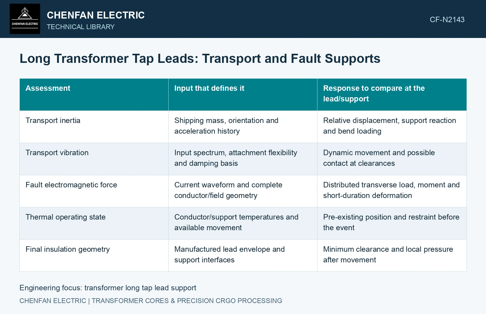
| Assessment | Input that defines it | Response to compare at the lead/support |
|---|---|---|
| Transport inertia | Shipping mass, orientation and acceleration history | Relative displacement, support reaction and bend loading |
| Transport vibration | Input spectrum, attachment flexibility and damping basis | Dynamic movement and possible contact at clearances |
| Fault electromagnetic force | Current waveform and complete conductor/field geometry | Distributed transverse load, moment and short-duration deformation |
| Thermal operating state | Conductor/support temperatures and available movement | Pre-existing position and restraint before the event |
| Final insulation geometry | Manufactured lead envelope and support interfaces | Minimum clearance and local pressure after movement |
A simple span calculation identifies sensitivity
For a uniform, simply supported elastic beam under transverse distributed load q, maximum static deflection is δ = 5qL⁴/(384EI). q is in N/m, span L in metres, Young’s modulus E in Pa and second moment I in m⁴; δ is in metres. The equation assumes small displacement, constant section and the stated end restraints.
As an illustrative comparison, increasing span from 0.40 m to 0.60 m while holding q, E and I fixed increases calculated deflection by (0.60/0.40)⁴ = 5.0625. This ratio explains why a seemingly modest support relocation deserves attention. It does not establish the deflection of a stranded, bent or paper-wrapped tap lead.
Dynamic transport loading needs its dynamic response, and a short fault pulse may not reach a static response. Neither is qualified by inserting an arbitrary peak force into the static equation. Use a representation capable of preserving the actual lead compliance and event duration.
Carry reactions into the insulation
A support can remain intact while allowing the lead to move into another electrical boundary. Compare displaced shapes with nearby conductors, grounded structures and barriers, including tolerances. Check local contact at the support as well: a narrow bearing region can transmit high pressure even when the overall reaction appears modest.
Define how the restraint behaves in each direction. Sliding, rotation and possible separation can change the load path. A model with a fully fixed clamp may overstate local moment and understate lead travel; an unrealistically free joint can make the opposite error.
Select supports from event-specific displacement and reactions. Verify dielectric interfaces and thermal movement with the local lead geometry under both transport and fault duties.
Screen a proposed increase in unsupported span
Keep stiffness, load path and joint geometry in the restraint or fastening assessment [2].
The assumed simply supported beam comparison from 0.40 m to 0.60 m multiplies static deflection by 5.0625 at unchanged distributed load and EI. If the reference deflection is assumed 0.50 mm, the longer-span result is 2.531 mm. Against an assumed 2.0 mm static-displacement allocation, the original 0.50 mm passes and the 2.531 mm longer-span result fails. Resolve actual strand/wrapping compliance and transient response before relocating the support.
References
- M. J. Casiano, Extracting Damping Ratio From Dynamic Data and Numerical Solutions, NASA/TM-2016-218227, September 2016, sections 1 and 1.5.
- R. T. Barrett, Fastener Design Manual, NASA Reference Publication 1228, 1990.