

Glass-epoxy bracket inspection must distinguish pulled fibres, local delamination and dimensional errors. Register those features at the loaded and high-field regions to qualify the machined part. [1]
Calculation basis. Project-specific values and gates in the illustrative screens below are assumptions; cited catalogue values retain their source test conditions.
Primary GFRP edge-milling experiments distinguish protruding fibers, resin damage, layer peeling and tool wear. The studied laminates and tools do not qualify a transformer bracket, but the distinctions help build an inspection vocabulary that is more useful than “good finish.”
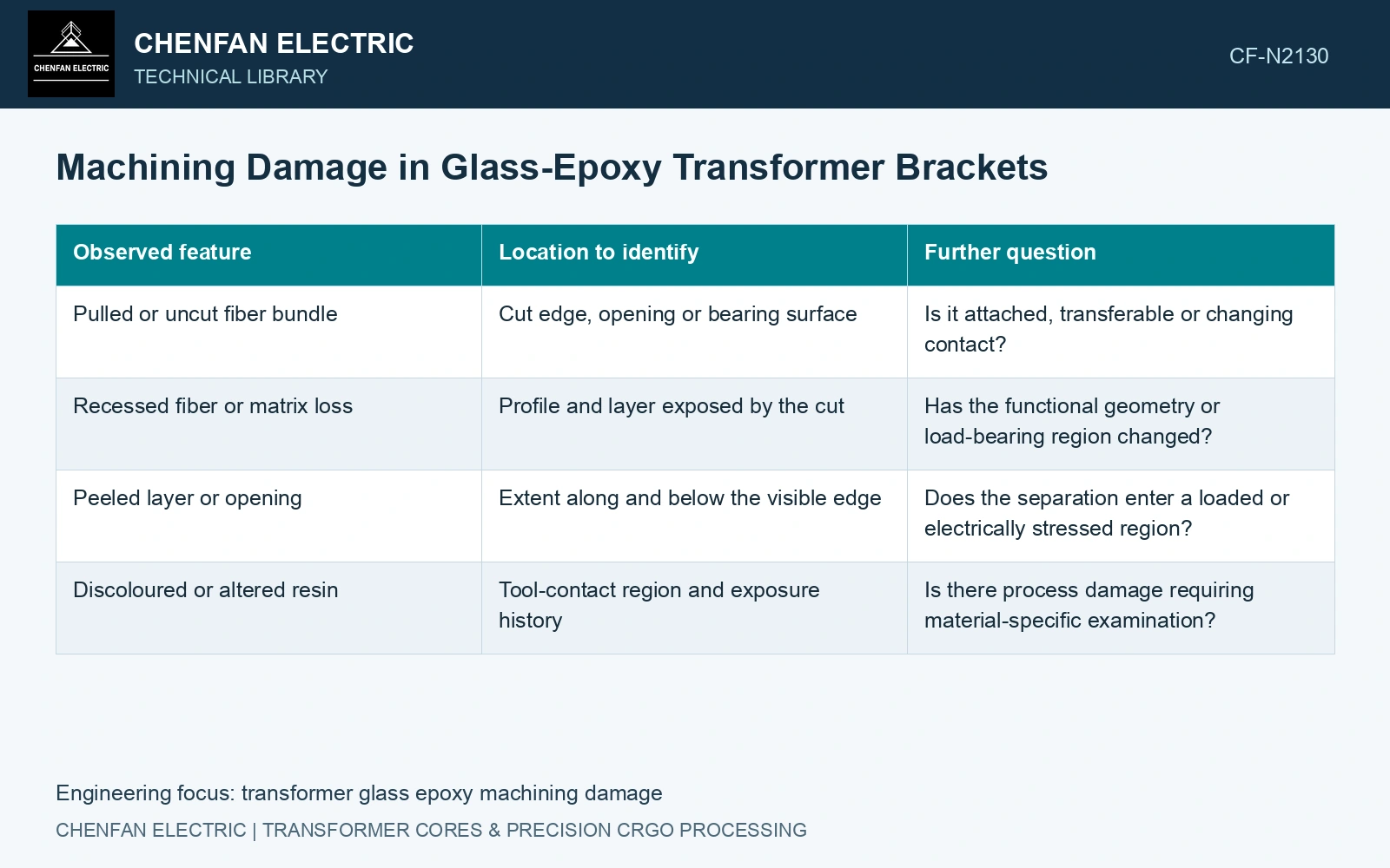
Map the defect to the bracket duty
| Observed feature | Location to identify | Further question |
|---|---|---|
| Pulled or uncut fiber bundle | Cut edge, opening or bearing surface | Is it attached, transferable or changing contact? |
| Recessed fiber or matrix loss | Profile and layer exposed by the cut | Has the functional geometry or load-bearing region changed? |
| Peeled layer or opening | Extent along and below the visible edge | Does the separation enter a loaded or electrically stressed region? |
| Discoloured or altered resin | Tool-contact region and exposure history | Is there process damage requiring material-specific examination? |
Record image scale, lighting and the reference geometry. A protruding bundle and a shallow resin recess can produce similar roughness statistics while having different mechanical and cleanliness consequences.
Reach below the surface where necessary
Representative sections can expose separation that an edge photograph misses. Prepare them with a documented method and compare the original surface images so examination damage is distinguishable from the machining defect.
Choose qualification features matching the bracket thickness, reinforcement arrangement and opening geometry. A thin straight edge cannot represent a deep hole wall or a re-entrant corner. Include the relevant tool condition rather than relying only on a fresh-tool witness.
For a loaded surface, evaluate seating and local bearing with the damaged region in the actual contact path. For an electrically exposed surface, preserve its position relative to conductors, oil space and potential boundaries. Visual classification alone supplies no discharge or withstand criterion.
Surface cleaning and structural correction are separate actions. Removing loose residue does not restore a missing profile or close an internal layer separation. Likewise, smoothing a region can alter dimensions or expose new reinforcement; it requires an approved, qualified route rather than an improvised repair.
Keep machining-temperature interpretation specific to the thermosetting resin system [2]. A cured thermoset epoxy does not behave like a thermoplastic that simply melts and resolidifies. Do not infer an acceptable process temperature from a generic melting label or the appearance of a polished cut.
Combine defined defect categories with dimensional, mechanical and electrical evidence. Extend the examination to the relevant duty when damage enters a load contact or high-field surface.
Compare the machined residual section before assessing concentration
Identify the actual epoxy-laminate construction and reinforcement within its material specification [2].
Assume milling damage reduces a glass-epoxy bracket’s effective 8.0 mm thickness to 7.2 mm over the loaded section. For unchanged width and bending moment, nominal bending stress scales with 1/t² and rises by (8/7.2)² − 1 = 23.46%. Assume a baseline nominal bending stress of 40 MPa and a 45 MPa project allocation. The reduced-section screen becomes 49.38 MPa and fails that assumed allocation. Inspect delamination and fibre direction before assigning intact-stock properties or approving a surface repair.
References
- A. Knap, Š. Dvořáčková and T. Knápek, Study of the Machining Process of GFRP Materials by Milling Technology with Coated Tools, Coatings 12, 1354, 2022, sections 2 and 3.1. DOI: 10.3390/coatings12091354.
- IEC, IEC 60893-3-2:2003+AMD1:2011, Insulating materials — Industrial rigid laminated sheets based on thermosetting resins for electrical purposes — Part 3-2: Specifications for individual materials — Requirements for rigid laminated sheets based on epoxy resins.