

Paint runs or bridges between closely spaced fins can reduce a cooling passage. A thickness reading on the outside face may not detect that obstruction. Coating inspection should include the final open geometry and the hard-to-reach regions. [1]
Mark fin spacing, depth and the direction of airflow in the design. Identify where spray overlap or drainage can accumulate film. Use the actual fin arrangement rather than assuming all passages are visible from one end.
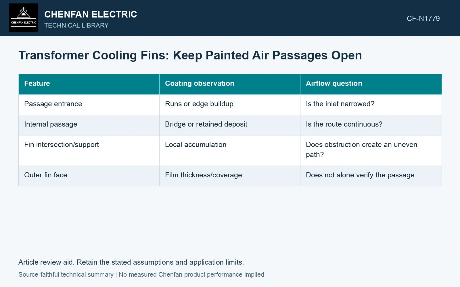
| Feature | Coating observation | Airflow question |
|---|---|---|
| Passage entrance | Runs or edge buildup | Is the inlet narrowed? |
| Internal passage | Bridge or retained deposit | Is the route continuous? |
| Fin intersection/support | Local accumulation | Does obstruction create an uneven path? |
| Outer fin face | Film thickness/coverage | Does not alone verify the passage |
Compare the remaining geometry
For a simple opening, remaining area can be recorded as Aopen = Adesign − Aobstructed, using m². This documents blockage; it does not directly predict cooling loss. Air distribution depends on passage resistance, buoyancy or forced-flow conditions and the surrounding arrangement.
A small bridge in a critical location can have a different effect from evenly distributed film buildup. Record position and connectivity, not only total obstructed area.
The operating airflow is set by fan pressure and passage resistance together. Continuity relates mean velocity to open area; it does not hold volume flow constant when that resistance changes. [2]
Quantify the blocked passage geometry
Assumptions: open area is initially 0.020 m² and paint bridges remove 0.003 m², leaving 0.017 m² (15% less). Air density is 1.2 kg/m³ at 20 °C; lumped passage loss coefficient K = 1, and fan pressure is 100 − 1000q² Pa for q in m³/s. Equating that pressure to Kρ(q/A)²/2 gives q = √[100/(1000 + 0.6/A²)]. Flow is 0.2000 m³/s before bridging and 0.1803 m³/s afterwards, a 9.85% reduction. Against an assumed qualified minimum airflow of 0.1900 m³/s, the coated passage fails by 0.0097 m³/s. Remove/rework the bridge and verify the final path. This fixed-coefficient forced-flow model does not convert the 15% blockage directly into lost heat capacity. [2]
References
- ISO, ISO 12944-7:2017, Paints and varnishes — Corrosion protection of steel structures by protective paint systems — Part 7: Execution and supervision of paint work.
- U.S. Department of Energy, DOE-HDBK-1012/3-92, Thermodynamics, Heat Transfer, and Fluid Flow, Volume 3, 1992.