

Eddy-current signals from a cooler tube can reflect flaws, probe coupling, dents, magnetic deposits or supports. The IAEA tube-testing manual explains how these responses differ with frequency and geometry [1]. Use a matched reference piece and a component-specific procedure before classifying a support-region indication.
Identify alloy, diameter, wall, construction and access. Conventional eddy-current assumptions suitable for one nonferromagnetic tube do not automatically fit another material or a double-wall assembly. Select and qualify the technique for that construction.
Use a location-aware signal ledger
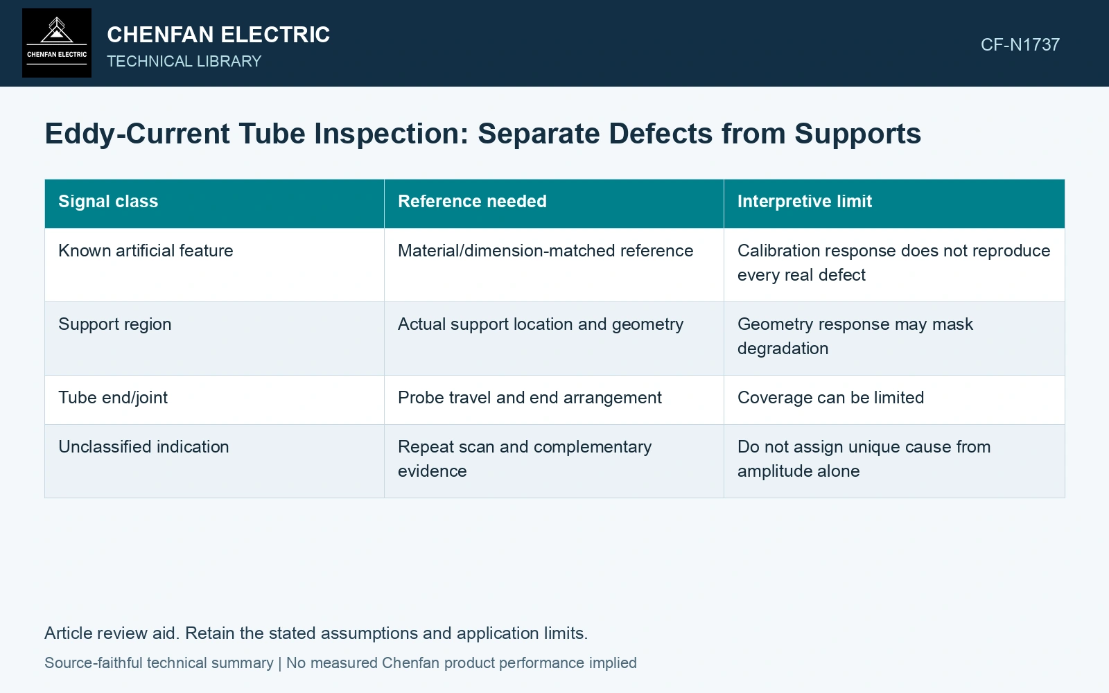
| Signal class | Reference needed | Interpretive limit |
|---|---|---|
| Known artificial feature | Material/dimension-matched reference | Calibration response does not reproduce every real defect |
| Support region | Actual support location and geometry | Geometry response may mask degradation |
| Tube end/joint | Probe travel and end arrangement | Coverage can be limited |
| Unclassified indication | Repeat scan and complementary evidence | Do not assign unique cause from amplitude alone |
Check what the probe can and cannot see
Record inspection speed, probe type, frequencies and the coverage actually achieved. Define which walls or surfaces the method is sensitive to in a double-tube cooler. The second wall and interspace can alter the response; a single-wall reference is not automatically adequate.
Separate signal detection from sizing and acceptance. A feature may be detected without its depth being reliably estimated. Conversely, a low signal can reflect unfavorable geometry or access rather than an intact wall.
ISO 20890-5 defines mechanised bore-side testing for non-ferromagnetic steam-generator tubes [2]. That defined scope does not qualify another alloy, a magnetic tube or a second wall in a transformer cooler. State which wall and flaw orientations the cooler procedure actually demonstrates.
Quantify the support-related blind lengths
Assume 20 tubes, each 3 m long, with two non-overlapping support intervals per tube. Each interval has 0.10 m axial length for which the required flaw sensitivity remains unproved. Unresolved length is 20 × 2 × 0.10 = 4 m out of 60 m, or 6.67%. This is an axial coverage inventory, not circumferential coverage or detection probability. Retain those intervals for a qualified complementary examination before closing the inspection scope.
References
- International Atomic Energy Agency, Eddy Current Testing at Level 2, Training Course Series 48, 2011, sections 5.2.2 and 6.3.
- ISO, ISO 20890-5:2020, Guidelines for in-service inspections for primary coolant circuit components of light water reactors — Part 5: Eddy current testing of steam generator heating tubes.