

A shell-form corner closes a magnetic route around the window. The sequence can use sheets that look similar but have different layer positions or overlap roles. Substituting them based only on their outer dimensions can preserve the visible outline while changing the internal closure.
Create a layer map from the approved design. Identify each sheet pattern, its orientation and its mating relationship at the corner. Mark shared and returning paths so that the map describes magnetic continuity rather than merely a parts list.
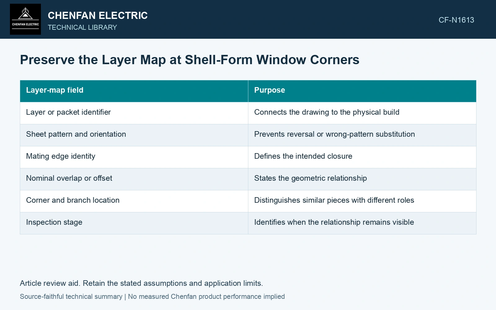
Record what closes at each layer
| Layer-map field | Purpose |
|---|---|
| Layer or packet identifier | Connects the drawing to the physical build |
| Sheet pattern and orientation | Prevents reversal or wrong-pattern substitution |
| Mating edge identity | Defines the intended closure |
| Nominal overlap or offset | States the geometric relationship |
| Corner and branch location | Distinguishes similar pieces with different roles |
| Inspection stage | Identifies when the relationship remains visible |
Follow a representative magnetic path through the layer and into the return region. Confirm that the intended joint closes where specified and that no sheet substitution introduces an unintended continuous seam or opening across the pattern.
This is a geometric review. The magnetic effect of a changed sequence depends on the complete field and material arrangement; do not assign a universal loss increase to a mislabeled sheet without analysis.
Define interchangeability by function
Two sheet patterns are interchangeable only if the approved design permits the substitution and the relevant geometry, direction and joint role remain equivalent. Similar area or weight does not prove that equivalence. Rolling-direction orientation can also matter when a piece is rotated.
Use clear identifiers at picking and placement. Where a shape can be assembled in more than one orientation, identify the intended reference edge or an approved error-prevention feature. Avoid adding markings or physical changes that affect the steel or insulation without process approval.
Inspect buried relationships before the next packet covers them. Associate photographs or coordinates with the layer map. An outer-edge check after closure cannot verify every internal offset.
Handle a sequence discrepancy explicitly
If a wrong pattern or orientation is found, identify the affected layers and the stage at which they became covered. Compare the actual arrangement with the approved map before deciding how far to reopen the stack. A nominal external profile does not eliminate the discrepancy.
After correction, repeat the affected geometric checks and update the layer identity record. If the design intentionally changes, review its magnetic and assembly consequences rather than treating it as a shop-floor substitution.
The map makes a corner sequence reproducible and inspectable. Its value is that the assembler can name the exact layer relationship at issue, instead of arguing from a finished outline that provides no view of the hidden closure.
Check layer build before closing the corner
Nippon Steel lists 0.23 mm nominal thickness with ±0.02 mm thickness tolerance for the selected GOES stock [1]. Assume a 100-sheet corner packet, excluding coating-build corrections, and an available insertion allowance of 24.0 mm. Nominal steel build is 100×0.23 = 23.0 mm. A deliberately conservative same-sign tolerance sum reaches 100×0.25 = 25.0 mm, exceeding the allowance by 1.0 mm. Use measured batch thickness and the actual layer schedule to resolve the fit before closure; do not infer hidden overlap or clearance from the finished outer profile.
Corner closure is controlled by sheet-pattern identity, rolling-direction orientation, layer overlap, edge straightness, cut burr and packet registration. Thickness sorting and packet build measurement control the physical fit, while the approved joint map controls magnetic continuity. The catalogue stock tolerance is not an assembled-core acceptance criterion. Keep the measured geometry, its reference state and its uncertainty together when evaluating the fit [2].
References
- Nippon Steel Corporation, Grain-Oriented Electrical Steel Sheets, catalogue D004je_03_202004, 2020, Specifications; Size and Form Tolerances.
- JCGM, JCGM 100:2008, Evaluation of measurement data — Guide to the expression of uncertainty in measurement, 2008.