Магнитопроводытрансформаторов.Изготовление по вашему чертежу.
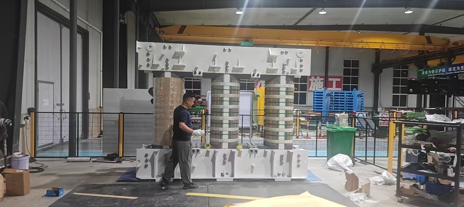
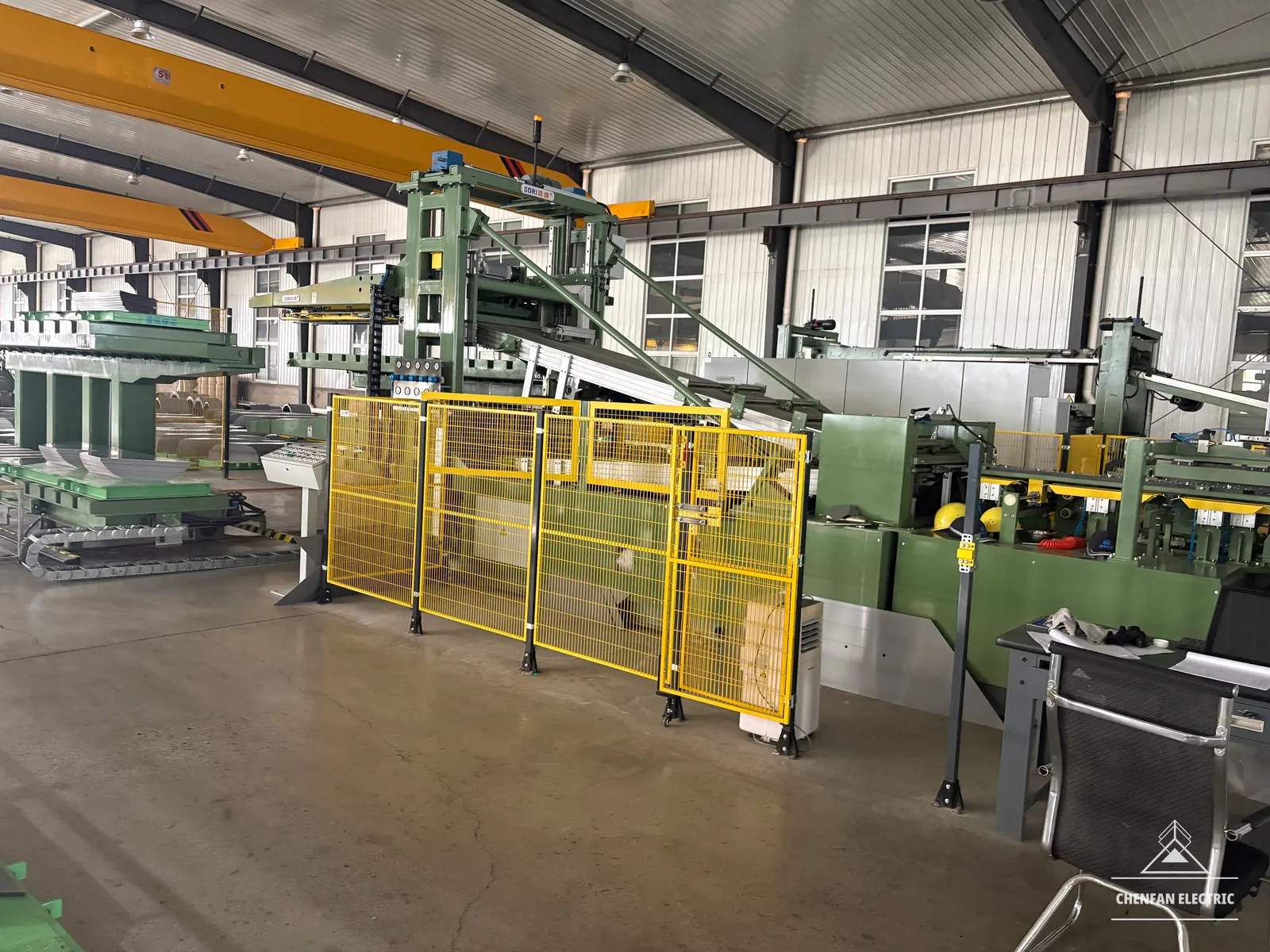
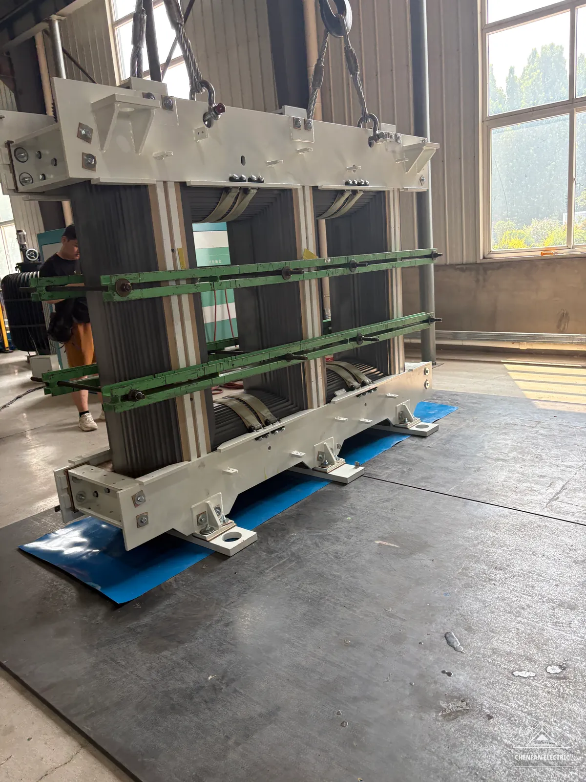
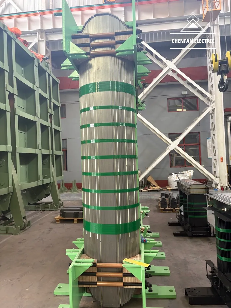
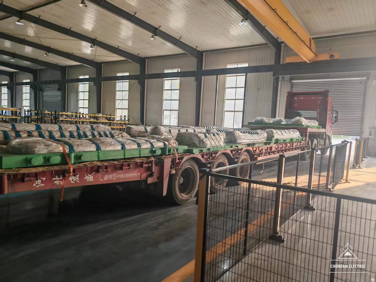
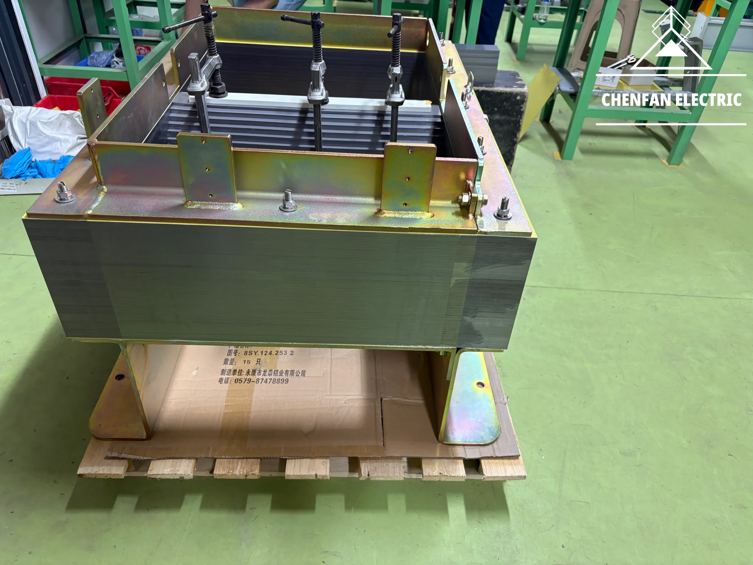
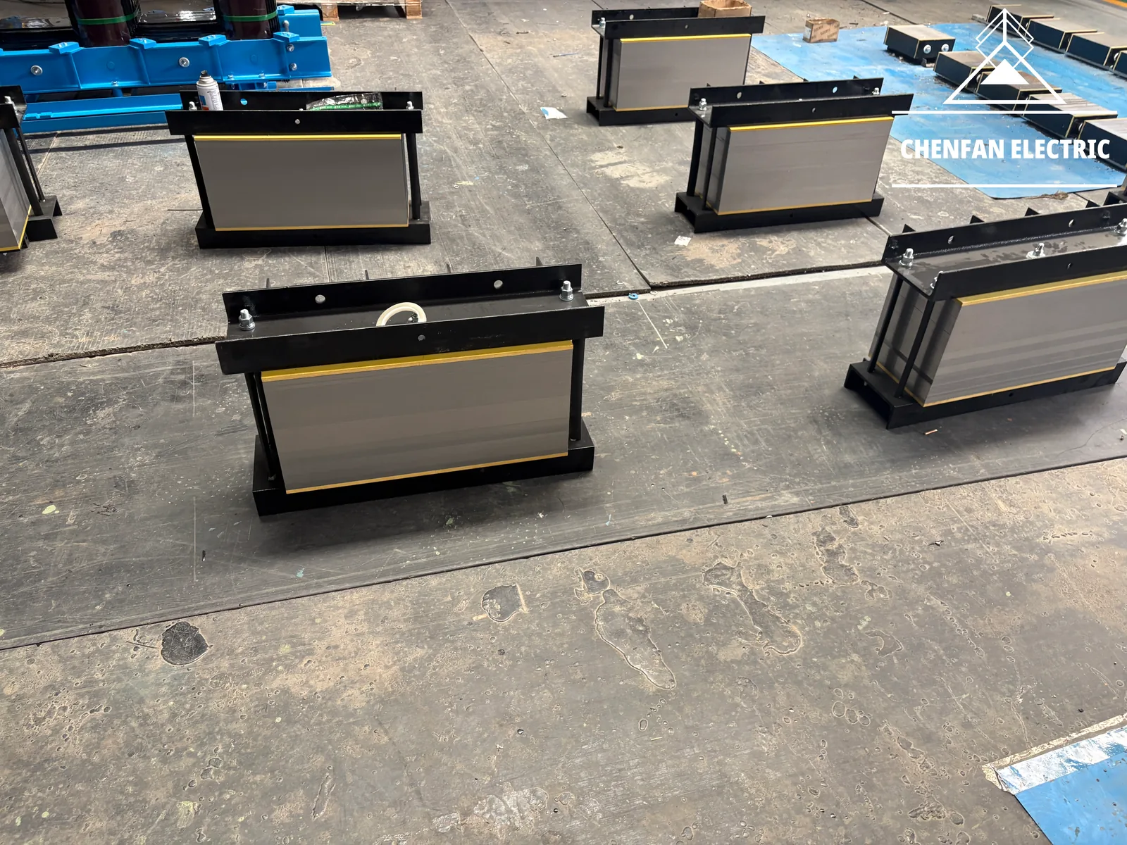
Производитель магнитопроводов трансформаторов: продольная резка CRGO, резка для ступенчатого стыка Step-Lap, предварительный набор пакетов и сборка магнитопроводов массой до 100 t.
Магнитопроводы трансформаторов и CRGO для производителей по всему миру. От электротехнической стали со склада до готовых магнитопроводов массой до 100 t — наше производство охватывает подготовку материала, точную резку, сборку и экспортную упаковку.
890mmМаксимальная ширина материала при поперечной резке
~3000tПостоянный запас CRGO
~1500tМощность обработки в месяц
15 летОпыт в отрасли
~USD 30 млнГодовой объём продаж
~7 днейСрок поставки стандартной продукции
ISO 9001:2015Система менеджмента качества
О Chenfan
Chenfan Electric объединяет производство магнитопроводов трансформаторов, обработку CRGO и поставки по всему миру. При годовом объёме продаж около USD 30 млн, постоянном запасе CRGO 3,000 t и мощности обработки 1,500 t в месяц мы обеспечиваем производство от подбора материала до поставки готового магнитопровода. Наши производственные возможности достигают 100 t на один магнитопровод при высоте заусенца менее 0.02 mm и коэффициенте заполнения сталью выше 97%.
02 Что мы производим
Изготовление магнитопроводов. От стали до сборки.
01
Магнитопроводы магнитопроводы
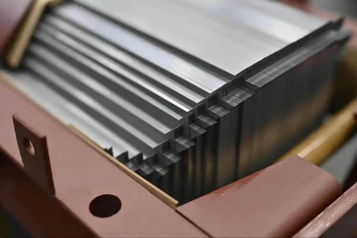
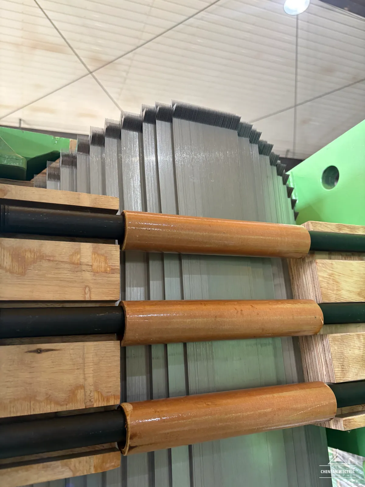
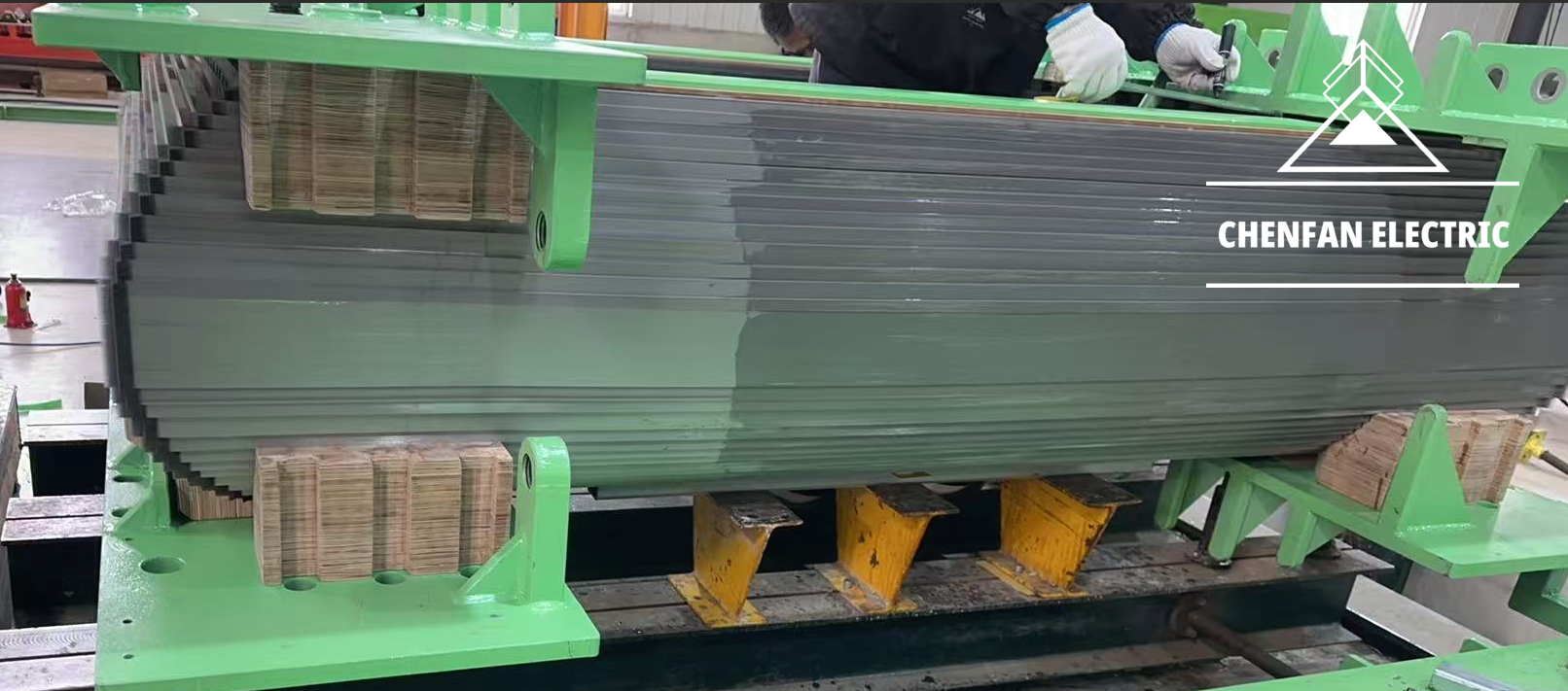
Многоступенчатые стыки Step-Lap, геометрия окон и сопряжения с прессующими конструкциями выполняются по утверждённому чертежу.
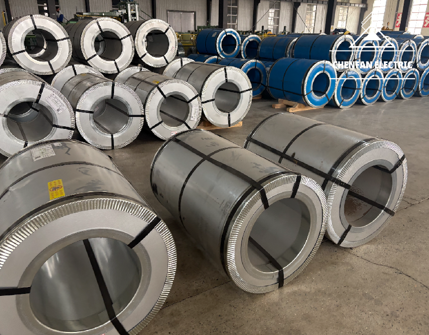
Холоднокатаная анизотропная электротехническая сталь требуемой для вашей конструкции трансформатора марки, толщины и с заданным покрытием, с идентификацией рулонов и сертификатами на материал.
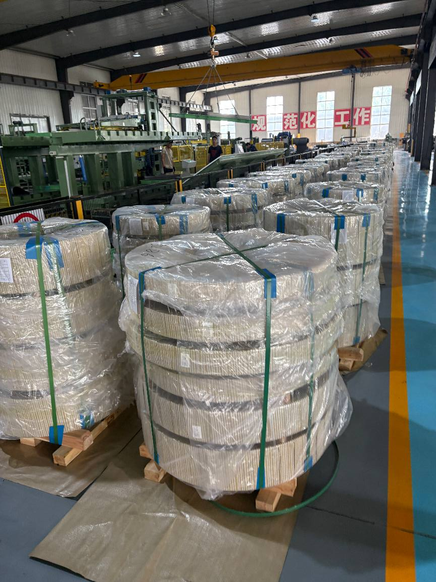
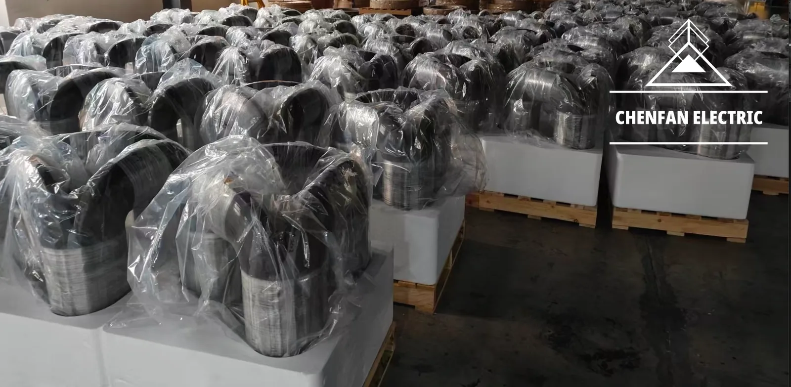
Материал и ширина лент по требованиям заказчика, обработка на линии продольной резки и защита с помощью специализированного автоматического упаковочного оборудования.
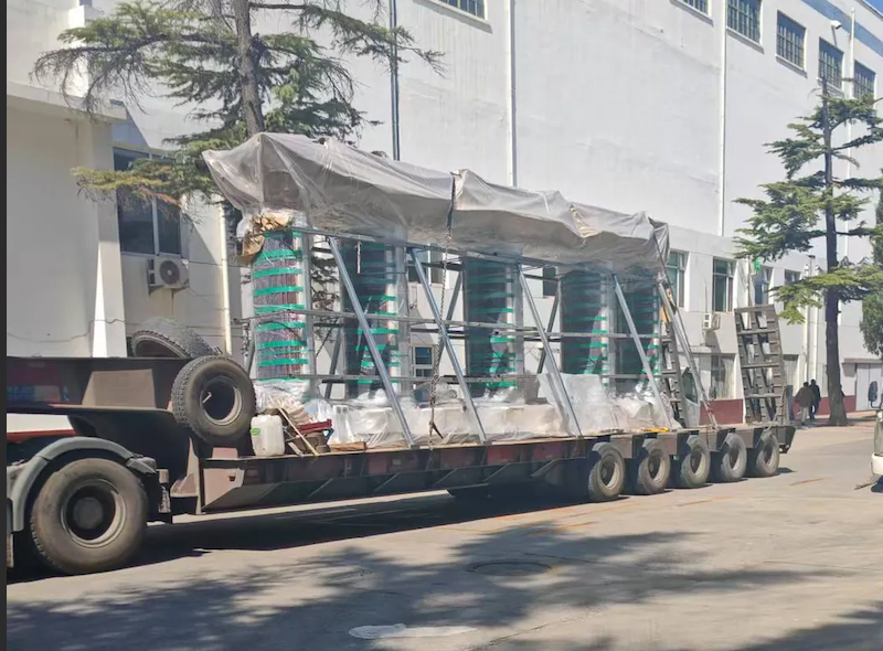
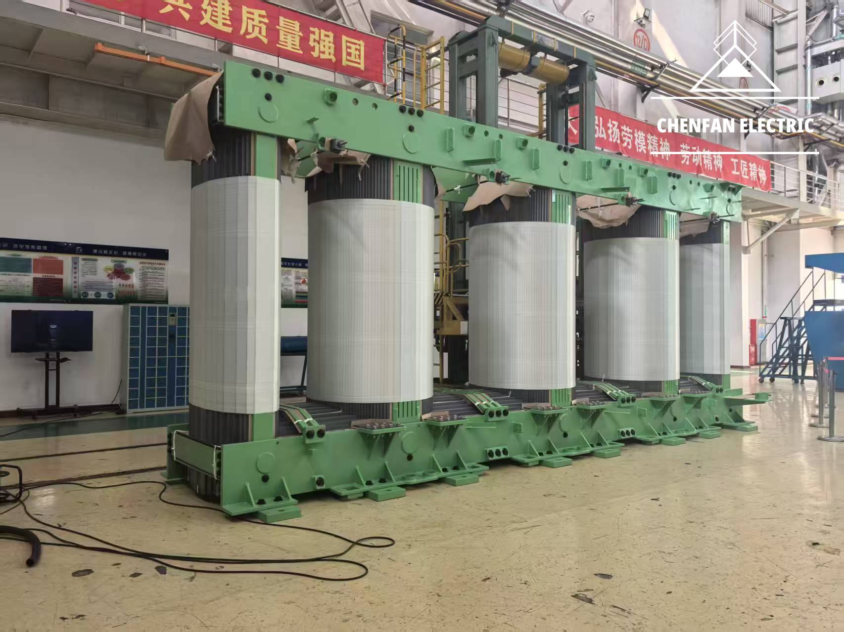
Изготовление тяжёлых магнитопроводов планируется как отдельный проект: устойчивость сборки, средства подъёма и транспортные крепления согласуются до начала работ.
Магнитопроводы силовых трансформаторов ↗
До 100 t на один магнитопровод
Выполнены проекты до 330 kV
Набранный магнитопровод / SKD / CKD
Материал
Сначала — спецификация. Затем — сталь.
Марки стали
Обычная GOES · Hi-B с высокой магнитной проницаемостью · С лазерной обработкой
Стандартная толщина
0.18 / 0.20 mm
Варианты для проекта
0.23 / 0.27 / 0.30 mm, по спецификации и при наличии материала
Набор из пластин электротехнической стали. Заданные сопряжения. Изучите трёхстержневой шихтованный магнитопровод — от пластин до стяжной конструкции.
01 / 05
Трёхстержневой шихтованный магнитопровод
Стержни и ярма набираются из ступенчатых пакетов холоднокатаной анизотропной электротехнической стали. Выберите метку на модели, чтобы изучить элемент конструкции.
Перетаскивайте для вращения · прокручивайте для изменения масштаба
Краткие ответы. Требования конкретного проекта подтверждаются при проверке чертежа и в коммерческом предложении.
Вы изготавливаете по чертежам заказчика?
Да. До начала производства мы проверяем утверждённый чертёж, спецификацию материала, последовательность стыков, объём сборки и критерии приёмки.
Какие форматы чертежей вы принимаете?
PDF, DWG и DXF. Укажите номер чертежа, редакцию и единицы измерения; после подготовки запроса отправьте файлы непосредственно Frank.
Какие толщины стали CRGO / GOES доступны?
Стандартные варианты: 0.18 / 0.20 mm. Толщина 0.23 / 0.27 / 0.30 mm доступна в соответствии со спецификацией проекта и наличием материала.
Вы поставляете магнитопроводы трансформаторов в полной сборке?
Да. Согласуйте прессовку, изоляцию, средства подъёма и транспортное состояние в соответствии с утверждённым чертежом.
Вы поставляете пластины магнитопровода, предварительно набранные в пакеты?
Да. Согласуйте маркировку пакетов, последовательность шихтовки, ответственность за сборку и требуемое состояние при поставке.
Какая информация нужна для коммерческого предложения?
Укажите номинальные параметры, приложите чертёж магнитопровода, укажите марку и толщину стали, вариант поставки, количество или массу, требуемые потери при наличии, условия поставки и пункт назначения.
Как контролируется высота заусенца?
Мы контролируем состояние режущих кромок инструмента и параметры процесса, а в ходе производства проверяем высоту заусенца. Текущие производственные возможности: <0.02 mm; метод контроля и план выборки необходимо согласовать.
Как оценивается коэффициент заполнения сталью?
Согласуйте способ сопоставления эффективной площади сечения или суммарной толщины стали с собранным пакетом. Текущие производственные возможности: >97%; материал, покрытие, давление прессовки и метод измерения подлежат согласованию.
Можно ли организовать измерение потерь в готовом магнитопроводе?
Запросите испытание на этапе проверки чертежа. До размещения заказа согласуйте состояние магнитопровода, схему возбуждения, частоту, магнитную индукцию, метод измерения и критерии приёмки.
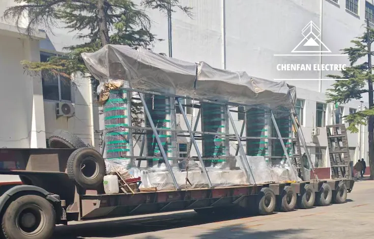
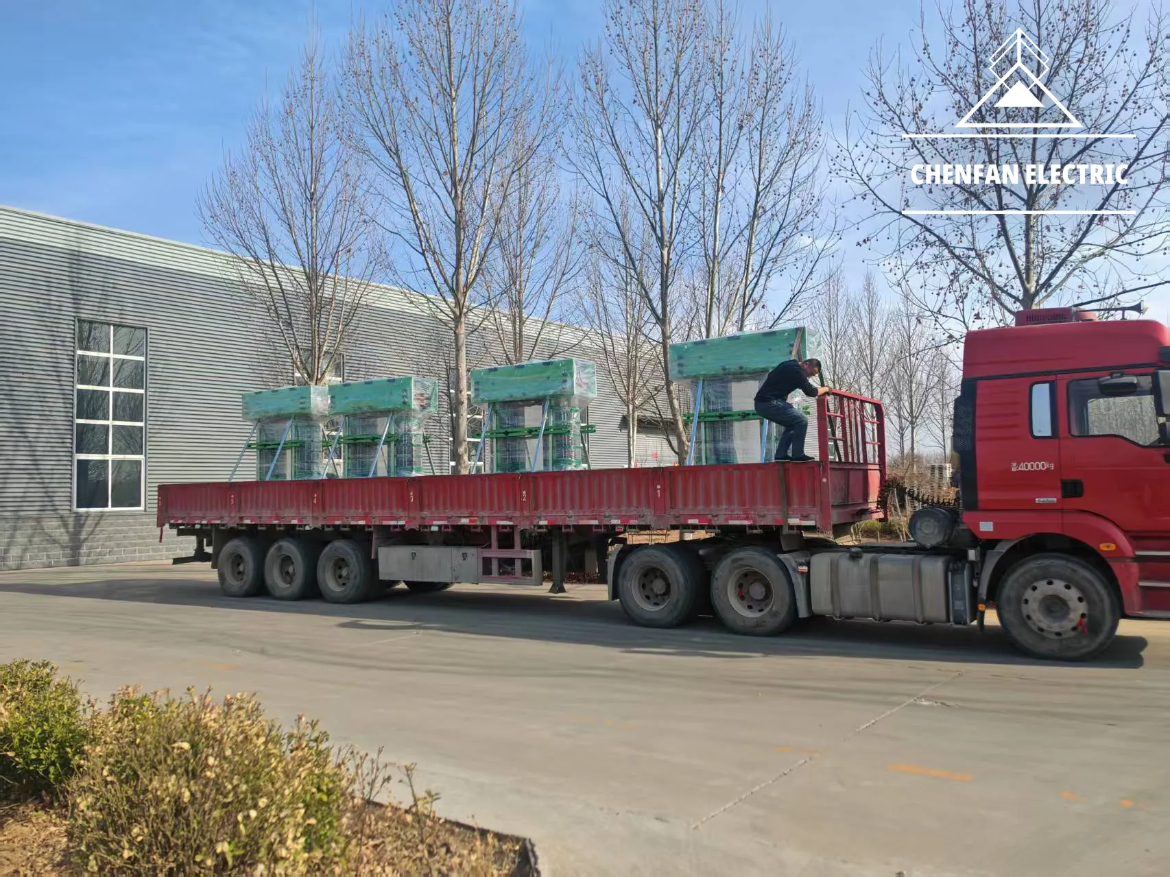
Как магнитопроводы трансформаторов защищают при морской перевозке?
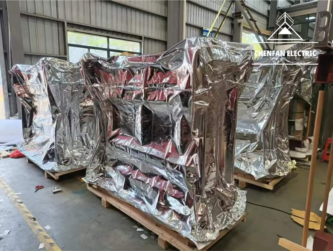
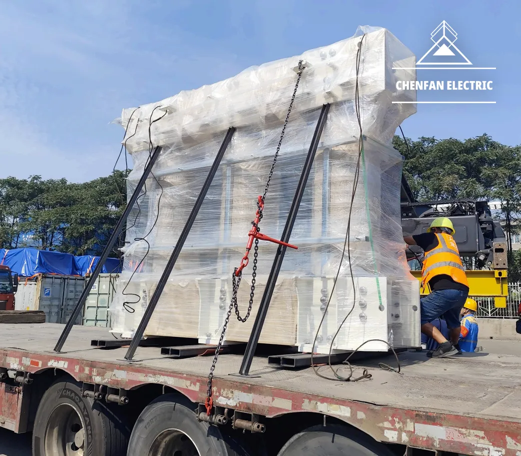
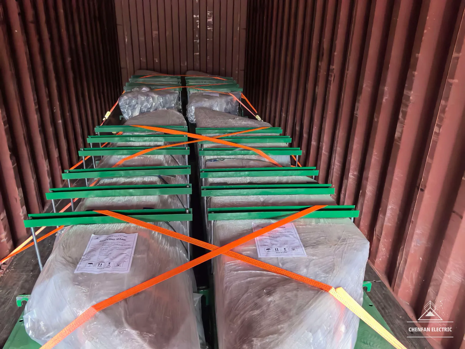
Упаковка сочетает влагозащиту, защиту кромок и крепления, подобранные с учётом геометрии и массы магнитопровода. Согласуйте маршрут, способ подъёма и условия разгрузки.
Вы изготавливаете крупные магнитопроводы силовых трансформаторов?
Производственные возможности позволяют изготавливать отдельные магнитопроводы массой до 100 t. Геометрия, устойчивость сборки, средства подъёма и условия транспортировки проверяются для каждого проекта.
Какие условия Incoterms доступны?
Возможны условия EXW, FOB и CIF. Укажите согласованное место или порт; иные условия требуют подтверждения в коммерческом предложении.
В первом ответе сообщаем о возможности изготовления, объёме поставки, цене и сроках. Запас CRGO около 3,000 t позволяет отгружать стандартную продукцию примерно за неделю.
When does a thinner lamination justify its material and processing cost?
Key Data
Compare specific loss at the same flux density, frequency and material test method.
JFE patent Table 1: at 1.7 T, 50 Hz and a 2 mm lap, 0.20 mm material gave 0.69 W/kg sheet loss and 0.86 W/kg core loss; 0.23 mm gave 0.73 and 0.92 W/kg respectively.
Technical Explanation
Thinner steel can reduce the classical eddy-current component of loss. Total core loss also depends on material grade, domain treatment, joint geometry and the mechanical condition after processing. Thickness alone therefore cannot establish the finished-core result.
The cited patent comparison used three-phase laboratory cores with five-step laps, a 15 mm stack and equal B8 of 1.91 T. It demonstrates a result under defined conditions, not a production guarantee or a ranking that applies to every pair of commercial grades.
For a given net steel build, thinner material requires more laminations. Handling, alignment and cutting workload change. The quotation should account for these operations and any change in effective steel area, rather than treating gauge as a simple substitution.
Engineering Implications
Compare suitable grades in both gauges against the actual loss target and operating frequency.
Review joint geometry and the expected stack build before freezing the material choice.
Procurement Implications
Evaluate the additional material and processing cost against the value of the expected finished-core loss reduction.
Request comparable core evidence where loss requirements are critical; a lower certificate value alone is insufficient.
What to Confirm Before Ordering
Grade, nominal thickness, coating and domain treatment.
Drawing, net steel area, excitation conditions and acceptance limits.
Test scope, reporting basis and any agreed material substitution.
How can building factor help compare cores without hiding differences in the test basis?
Key Data
BF = measured core loss ÷ reference material loss, with both expressed on a consistent basis.
If core loss is reported in watts, the reference in W/kg must be multiplied by the agreed steel mass before calculating the ratio.
Technical Explanation
Building factor describes the relationship between a manufactured magnetic circuit and its material reference. Cutting effects, joint flux distribution, assembly stress and geometry can all contribute to the difference. It includes design and manufacturing effects, so it cannot isolate supplier workmanship by itself.
The denominator needs an explicit definition. An actual coil measurement and a grade maximum are different references. Single-sheet and Epstein results must not be interchanged without an agreed, applicable method. Changing the reference can change the ratio even when the measured core watts stay the same.
A lower building factor does not automatically mean lower absolute loss. A core made from lower-loss material can have a larger ratio and still dissipate fewer watts. Read the ratio alongside measured loss and exciting current at the specified operating point.
Engineering Implications
Keep drawing, material basis, frequency, flux density and test arrangement consistent when comparing results.
Review consecutive comparable cores to understand variation rather than relying on one favourable result.
Procurement Implications
Write the denominator and mass basis into the acceptance requirements.
Keep the contractual loss limit separate from a supplier comparison based on building factor.
What to Confirm Before Ordering
Actual coil loss or grade maximum; material test method and any conversion.
Test frequency, flux density, waveform and measurement boundary.
Core mass, measured watts, exciting current and required report.
Why can cores made from the same CRGO grade deliver different magnetic performance?
Key Data
Mill certificate: evidence for the specified material and its recorded test results.
Finished-core report: evidence for the assembled core under a stated test arrangement.
Chenfan process parameters: burr height <0.02 mm; stacking factor >97%.
Technical Explanation
A mill test certificate identifies the starting material. Check the coil reference, grade, thickness and magnetic data against the order. The certificate does not describe the cutting, joint alignment, clamping or handling that takes place afterwards.
The finished core contains cut edges, overlapping joints and a mechanical stress state. Those conditions help explain why the same nominal grade and thickness can produce different loss and exciting-current results. A low burr reading and a high stacking factor are useful process indicators; neither is a standalone magnetic acceptance test.
Material tests on processed samples can support an investigation, provided sampling and specimen preparation are defined. Treatments such as stress-relief annealing can change what the comparison reveals. Finished-core testing must also have an agreed excitation method, calculation boundary and acceptance basis. It supports pre-shipment verification but does not replace the transformer manufacturer’s final testing.
Engineering Implications
Link the material certificate and process records to the supplied core or lamination batch.
Read no-load loss and exciting current together under comparable test conditions.
Procurement Implications
Agree the inspection and testing scope before ordering, including which reports will be supplied.
For critical designs, request evidence of repeatability across comparable production.
What to Confirm Before Ordering
Material traceability and certificate requirements.
Sample preparation, test frequency, flux density and reporting units.
Finished-core test availability, acceptance criteria and responsibility for final transformer testing.
Engineering definition
Engineering Question
Which drawing details must be agreed before a core is released for cutting?
The drawing must define the same physical product for the transformer designer and the core factory. Confirm usable window clearances against the winding, insulation and clamping arrangement. Distinguish clear window width from centre distance; they are not interchangeable dimensions.
Limb and yoke widths must include the complete stepped section or a controlled lamination schedule. Stack thickness needs a stated measurement condition: net steel build, finished physical thickness and thickness under compression describe different quantities.
Step geometry should identify packet widths, lamination quantities, orientation and joint sequence. Drawing revision control then fixes which combination is approved for production. A current CAD file and a controlled PDF can help resolve geometry, but neither removes the need to confirm unclear dimensions.
Overall assembled dimensions, clamp interfaces, lifting access and shipping envelope also belong in the review where applicable. They are supporting interface checks beyond the eight headline items.
Engineering Implications
Check winding fit and structural interfaces before converting the drawing into a cutting schedule.
Resolve conflicting dimensions and document approved deviations before production release.
Procurement Implications
Use estimated weight for preliminary discussion; confirm manufacturing geometry before final production planning.
Include the required supply format because laminations and fully assembled cores need different delivery definitions.
What to Confirm Before Ordering
Drawing number, revision, approval date and quantity.
Material grade, thickness, lamination schedule and joint arrangement.
Finished dimensions, tolerances, measurement conditions and included hardware.
Joint geometry
Engineering Question
What must be controlled for a step-lap design to deliver repeatable core performance?
Key Data
The manufacturing definition needs step sequence, lap length, joint gap and laminations per step.
Loss and exciting-current results require a stated frequency, flux density and core configuration.
Technical Explanation
A step-lap joint distributes lamination ends across successive positions. Magnetic flux redistributes between the overlapping sheets near those ends, creating a local field that differs from the field in a straight limb. Joint geometry therefore affects magnetic behaviour as well as mechanical assembly.
The benefit depends on the material, core design and manufactured joint. A larger number of steps is not a universal guarantee of lower loss, and the smallest achievable gap is not a complete specification. Lap length, gap, layer grouping and sequence must be considered together.
The JFE patent reports different core-loss results when lap length changes while material thickness is held constant in its laboratory configuration. This supports evaluating joint geometry alongside material selection; its particular dimensions should not be copied into an unrelated drawing.
Correct cutting dimensions must be preserved through stacking. Misalignment, mixed packets or an incorrect sequence can change the intended joint. Mechanical restraint must hold the assembly without introducing uncontrolled local pressure.
Engineering Implications
Define the complete joint schedule and check its reproduction through the stack.
Assess loss and exciting current; agree separate noise evaluation when it is a project requirement.
Procurement Implications
Ask for the joint definition behind the term “multi-step lap”.
For cut or pre-stacked supply, agree identification and assembly instructions so the receiving factory can preserve the sequence.
What to Confirm Before Ordering
Approved joint drawing, step count, grouping and sequence.
Dimensional tolerances, inspection points and assembly responsibility.
Test scope and acceptance requirements for the supplied format.
What does a burr-height requirement tell you about a cut CRGO lamination?
Key Data
Chenfan burr-height control: <0.02 mm.
Burr height is one edge-quality measurement; it is not a finished-core loss guarantee.
Technical Explanation
A burr is raised metal at a cut edge. Excessive burrs can interfere with stacking and, under contact pressure, damage insulation between laminations. Electrical contact between sheets can provide additional current paths and contribute to local heating or loss.
The risk depends on the edge condition, coating, alignment and assembly pressure. The specified limit is a manufacturing control value, not a universal boundary below which insulation damage is impossible. Visual appearance or a smooth feel cannot establish magnetic performance.
Tool wear, cutting clearance and material condition influence the edge produced by slitting and cross-cutting. A useful inspection plan defines where to measure, how samples represent the batch, which instrument is used and what action follows an out-of-limit result. A measured value needs that context to be comparable.
Cutting can also introduce local mechanical stress without producing an obviously large burr. Edge inspection should therefore sit alongside dimensional checks, coating inspection and any agreed magnetic verification.
Engineering Implications
Inspect representative cut edges and changes associated with tool condition.
Control handling and clamping so acceptable laminations remain protected during assembly.
Procurement Implications
Include the burr requirement and its inspection basis in the technical agreement.
Avoid treating a single edge reading as evidence that an entire core meets its loss limit.
What to Confirm Before Ordering
Material grade, thickness and coating specification.
Measurement method, sampling positions and reporting requirement.
Batch traceability and the agreed response to nonconforming laminations.
Core assembly
Engineering Question
How does stacking factor affect the magnetic section used in a core design?
Key Data
Chenfan stacking-factor control: >97%.
On a consistent section basis: effective steel area = gross stacked area × stacking factor.
Technical Explanation
Stacking factor expresses how much of a defined stack is occupied by steel. Insulation coating and spaces between laminations mean the gross physical section is not identical to the effective steel section. The design and inspection calculation must use compatible definitions.
At the same magnetic flux, a smaller effective steel area gives a higher flux density. This is why substituting a stack dimension or material thickness without checking the net steel build can change the magnetic operating point. The resulting loss and exciting current depend on the material and operating conditions.
The measured result also depends on the specimen or assembly being evaluated and its compression condition. A material sample value and a finished-assembly assessment should not be treated as identical without explaining the method.
Flatness, burrs, cleanliness, packet alignment and restraint all matter. Increasing clamp force alone is not a sound way to correct poor stacking: excessive or uneven stress can affect the magnetic material and the structure.
Engineering Implications
Use the agreed effective steel area when checking flux density and lamination quantities.
Check finished stack dimensions and joint alignment as well as the reported factor.
Procurement Implications
Agree how the >97% requirement is evaluated for the ordered product.
Keep stacking-factor acceptance distinct from finished-core loss acceptance.
What to Confirm Before Ordering
Net steel area, gross section and material thickness basis.
Measurement method, sample or assembly scope, and compression condition.
Finished stack tolerance, inspection records and magnetic test requirements.
Packing & delivery
Engineering Question
What must an export packing specification protect besides the outside of the case?
Key Data
Define supply format, packed mass, dimensions, support points and handling method.
Address moisture exposure and mechanical movement separately in the packing plan.
Technical Explanation
A transformer core should arrive with its surfaces, geometry and assembly identification preserved. Moisture protection limits corrosion risk, while supports and restraints limit movement, edge damage and distortion. A strong outer case does not by itself resolve either requirement.
The protection system should suit the route, storage period and receiving conditions. Specify a compatible moisture barrier and, where appropriate, corrosion protection and desiccant. VCI packaging is one possible component; it should not be described as an absolute barrier that makes rust impossible.
Restraints should transfer loads through suitable supports rather than relying on exposed lamination edges. The plan for a fully assembled core must account for its lifting arrangement and stability. Cut and pre-stacked laminations also need packet identification and protection of the intended assembly sequence.
Destination handling matters. Confirm how the package will be unloaded, stored and opened, including the equipment available at the receiving factory. Packing photos, identification and an agreed receiving inspection help resolve discrepancies before the core enters assembly.
Engineering Implications
Coordinate the packing arrangement with the core structure and approved lifting method.
Preserve critical dimensions, joint condition and assembly instructions through delivery.
Procurement Implications
Include packing requirements in the quotation instead of leaving them to dispatch.
Define transport scope, Incoterm, destination and any planned storage before installation.
What to Confirm Before Ordering
Supply format, case or frame arrangement, gross mass and package dimensions.
Moisture protection, restraints, marks and lifting instructions.
Unloading equipment, storage conditions, inspection documents and applicable wood-packing requirements.