

Fringing flux around a reactor gap can cross the lamination planes in a way the main limb flux does not. Radial packet arrangements are intended to change that local relationship. Their benefit must be evaluated together with the joints and manufacturing geometry they introduce. [1]
Draw the local flux direction in three dimensions and mark the plane of every sheet. The relevant question is whether a field component drives an eddy-current loop within conductive material or is interrupted by interlaminar insulation. A drawing that shows only the main axial flux misses the gap-end problem.
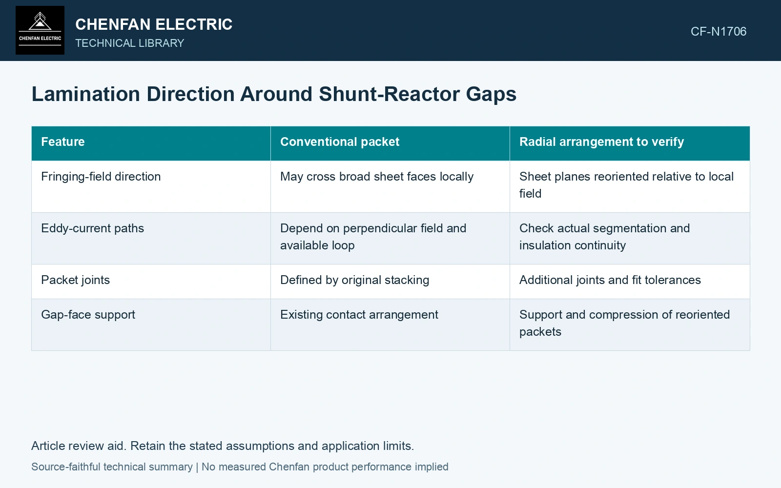
Compare both magnetic and manufacturing paths
| Feature | Conventional packet | Radial arrangement to verify |
|---|---|---|
| Fringing-field direction | May cross broad sheet faces locally | Sheet planes reoriented relative to local field |
| Eddy-current paths | Depend on perpendicular field and available loop | Check actual segmentation and insulation continuity |
| Packet joints | Defined by original stacking | Additional joints and fit tolerances |
| Gap-face support | Existing contact arrangement | Support and compression of reoriented packets |
Do not judge the concept from sheet orientation alone
A radial layout can alter local loss while also changing reluctance, contact and flux concentration near joints. Include the actual seams and edge geometry in the model. A perfectly continuous ideal radial geometry cannot represent a manufactured segmented assembly.
Use identical excitation and total gap when comparing arrangements. Separate core loss in the packets from heating in nearby clamps. If an arrangement moves fringing flux away from one packet but into a support, total and local benefits can differ.
Check the radial joint’s flux bottleneck
Nippon Steel’s GOES catalogue gives density 7.65 kg/dm³. [2] Assumptions: a uniform packet contains 50 kg steel along a 0.50 m magnetic path and carries 0.020 Wb peak at 50 Hz. Its inferred steel area is 50/(7,650 × 0.50) = 0.01307 m², giving 1.53 T. A proposed radial joint narrows the effective area to 0.010 m², raising local density to 2.00 T. Against an assumed 1.60 T local design ceiling, that joint fails by 0.40 T despite the original packet passing. Hold the radial design until joint area and field concentration are resolved; this volume/flux screen does not predict gap loss.
Rolling direction, sheet-plane orientation, joint neck area, cut edges and gap/spacer alignment all belong in the manufactured model. Reorienting a packet changes the local field relationship but can introduce seams and concentration. Verify local heating and preserve interlaminar insulation; the catalogue density used above supplies no transverse-loss or saturation allowance. [1]
References
- H. B. Duc, T. P. Minh, T. P. Anh and V. D. Quoc, A Novel Approach for the Modeling of Electromagnetic Forces in Air-Gap Shunt Reactors, Engineering, Technology & Applied Science Research 12, 8223–8227, 2022. DOI: 10.48084/etasr.4692.
- Nippon Steel Corporation, Grain-Oriented Electrical Steel Sheets, catalogue D004je, April 2020, specification and typical-property tables.