

Two grounding resistor assemblies can have the same ohmic value and different thermal duties. One may be designed to store fault heat for a limited interval; another may remove heat continuously at its specified current. Resistance alone does not distinguish them. [1]
The duty statement needs current, duration, initial condition and cooling assumptions. Those terms should follow the fault study and operating arrangement through every relevant component, rather than appear as an isolated seconds entry on a purchase order.
Ask where the heat goes
During short-time duty, element and surrounding material temperatures can rise as electrical energy accumulates. Continuous duty requires a sustainable heat balance under the stated ambient and enclosure conditions. A short-time capability cannot be divided by an arbitrary factor to obtain continuous capacity.
For a resistor with approximately constant resistance, power is I²R, in watts when I is amperes and R is ohms. Over time t in seconds, electrical energy is I²Rt in joules. Temperature-dependent resistance and changing current require the actual power history instead. These expressions quantify input heat, not the assembly’s allowable temperature.
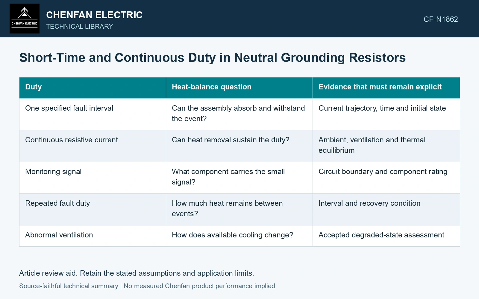
| Duty | Heat-balance question | Evidence that must remain explicit |
|---|---|---|
| One specified fault interval | Can the assembly absorb and withstand the event? | Current trajectory, time and initial state |
| Continuous resistive current | Can heat removal sustain the duty? | Ambient, ventilation and thermal equilibrium |
| Monitoring signal | What component carries the small signal? | Circuit boundary and component rating |
| Repeated fault duty | How much heat remains between events? | Interval and recovery condition |
| Abnormal ventilation | How does available cooling change? | Accepted degraded-state assessment |
Check more than the resistor element
Insulating supports, connections and adjacent controls see their own thermal environments. The hottest element need not identify the component with the smallest allowable margin. Radiation or a conductive contact can heat a support differently from the element’s average temperature.
Use a thermal-storage and heat-removal model to translate the specified event into temperature. The cooling boundary, thermal resistance and stored heat remain part of that calculation. [2]
Compare equal resistance under different durations
Assumptions: 10 A RMS through a constant 100 Ω gives 10 kW; 10 s and 60 s supply 100 kJ and 600 kJ. For a single thermal node initially at a fixed 40 °C cooling reference, assume Cth = 2 kJ/K and Rth = 0.020 K/W, giving τ = 40 s. Its temperature is 40 + 200[1 − exp(−t/40)] °C under constant input. The 10 s event reaches 84.24 °C, the 60 s event 195.37 °C, and continuous equilibrium 240 °C. Against an assumed 150 °C gate, only the 10 s case passes this screen. Specify the actual clearing and repeat sequence; a short-time record cannot establish the 60 s or continuous duty.
Keep continuous exposure in the service case
An operating arrangement that permits a persistent earth fault needs continuous-duty evidence appropriate to that condition. A limited-duration resistor cannot be assumed suitable merely because protection normally clears quickly. Review backup clearing and credible failure cases using the accepted system design.
References
- IEEE, IEEE C57.32-2015, IEEE Standard for Requirements, Terminology, and Test Procedures for Neutral Grounding Devices (historical edition).
- U.S. Department of Energy, DOE-HDBK-1012/2-92, Thermodynamics, Heat Transfer, and Fluid Flow, Volume 2, 1992.