

Covering an exposed lamination edge can restore a visible barrier while creating a new mechanical connection. If the coating bridges a step-lap interface or fills a clearance, it may restrict movement or change seating. The repair needs to preserve isolation and the geometry that the assembly uses.
Identify the original damage and the proposed coverage volume. A boundary drawn only on a surface is incomplete if material can enter an overlap or bond neighboring layers. Include the cured coating thickness and the regions where joint movement must remain possible.
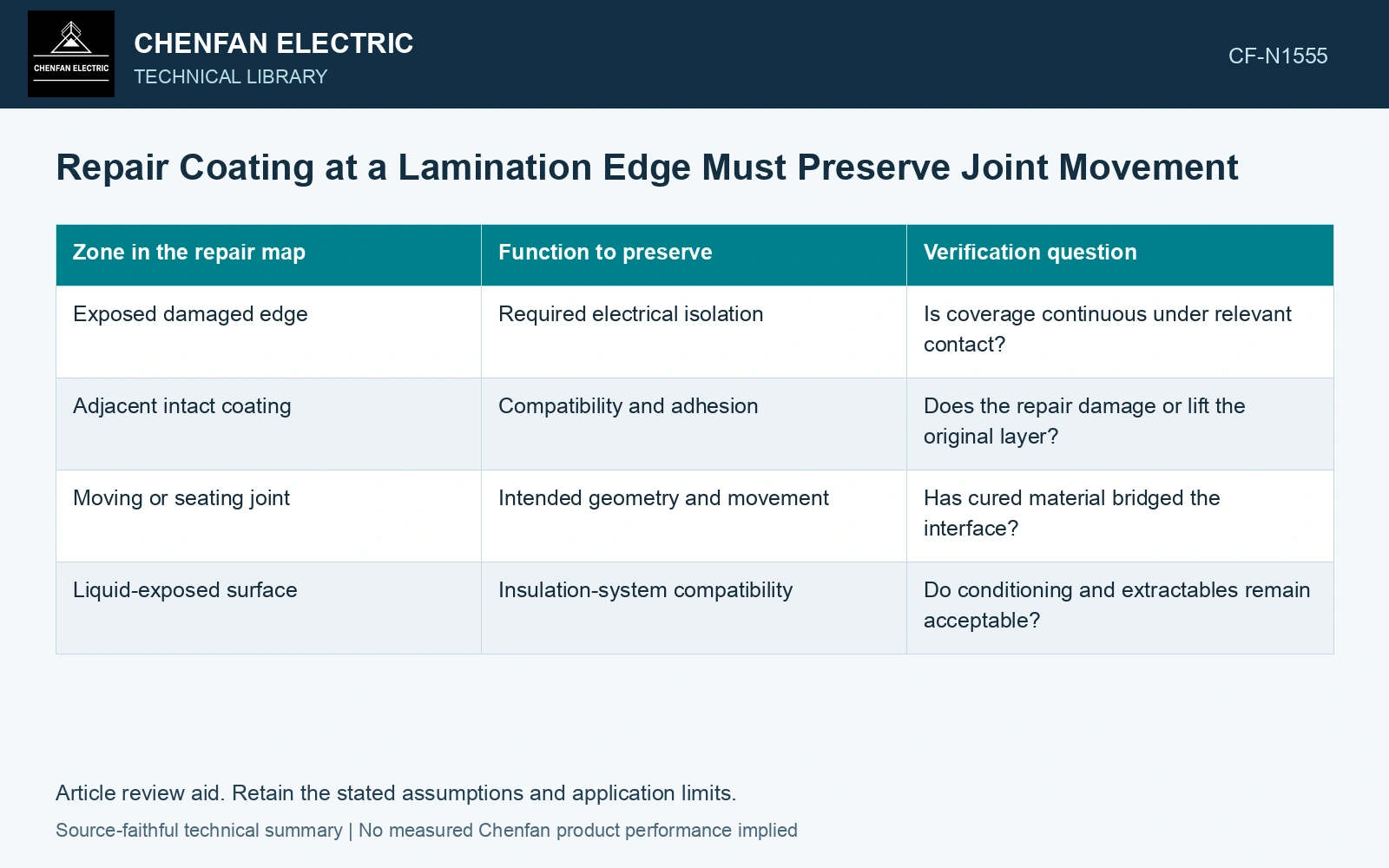
Map coverage and movement separately
Mark surfaces requiring electrical isolation and interfaces requiring clearance or relative movement. Where those requirements meet, the design should specify how the repair avoids creating an unintended bridge. The inspection needs access to the final condition, not only the wet application pattern.
| Zone in the repair map | Function to preserve | Verification question |
|---|---|---|
| Exposed damaged edge | Required electrical isolation | Is coverage continuous under relevant contact? |
| Adjacent intact coating | Compatibility and adhesion | Does the repair damage or lift the original layer? |
| Moving or seating joint | Intended geometry and movement | Has cured material bridged the interface? |
| Liquid-exposed surface | Insulation-system compatibility | Do conditioning and extractables remain acceptable? |
The map should be connected to the actual drawing and material system. A general description such as insulating varnish cannot supply these answers.
Qualify the complete material combination
Evaluate adhesion to the actual substrate and original coating after the approved preparation. Identify failure location rather than reporting only a breaking force. The repair’s cure and subsequent exposure history must represent the proposed use.
Where the assembly uses insulating liquid, examine both the repaired material and the liquid through appropriate controlled comparisons. Mechanical survival in oil does not establish that the material leaves the liquid unchanged. Conversely, acceptable liquid measurements do not demonstrate that the coating remains attached.
Test the electrical interface under a defined state
Choose measurements relevant to the repaired interlaminar path. Record contact geometry, load, temperature and test conditions. A surface may appear continuously covered while an inaccessible contact or thin region remains electrically significant.
Check geometry and movement after conditioning. A coating that initially leaves a gap may migrate or change shape during cure, loading or thermal history. A representative trial should examine the state in which the joint will function.
State what has been restored
The record should identify the repaired region and the functions demonstrated there. If the original factory coating performance cannot be reconstructed or directly compared, state the qualified repaired function rather than claiming that the original material system has been recreated.
Repair acceptance follows the combined electrical, material and mechanical evidence. A uniformly colored edge is useful for locating coverage, but it cannot show whether the repair preserves an active joint, survives the relevant conditioning, or eliminates every conductive return through the packet.
Budget cured coating against the actual seating gap
Catalogue nominal sheet thickness is 0.23 mm [1]. Assume a 0.10 mm functional seating gap and an applied repair coating that cures to 0.040 mm on each opposing face. The cured stack consumes 0.080 mm and leaves only 0.020 mm, equivalent to 8.7% of a nominal sheet thickness. With assumed expanded thickness uncertainty of 0.015 mm per face and a conservative additive allowance, the upper coating build is 0.110 mm, exceeding the gap by 0.010 mm [2]. Mask or redesign the coverage boundary and requalify the assembled geometry. This calculation addresses fit; it does not qualify dielectric performance or material compatibility.
Manufacturing controls. Application coverage, cured thickness, joint-step placement, clamping and cure shrinkage control mechanical bridging. Qualification must preserve electrical separation and intended seating movement under the relevant conditioning history.
References
- Nippon Steel Corporation, Grain-Oriented Electrical Steel Sheets, catalogue D004je_03_202004, 2020, Specifications; Size and Form Tolerances.
- JCGM, JCGM 100:2008, Evaluation of measurement data — Guide to the expression of uncertainty in measurement, 2008.