

For two otherwise electrically isolated laminations, one conductive bridge joins them but does not by itself create a closed loop through both sheets. A second connection can complete the path. The loop then includes portions of each sheet and the two bridges.
This simple illustration is useful because it makes the return path explicit. A real packet can contain other connections through debris, damaged coating, a joint or nearby conductive structures. An apparently single bridge may therefore belong to a larger circuit.
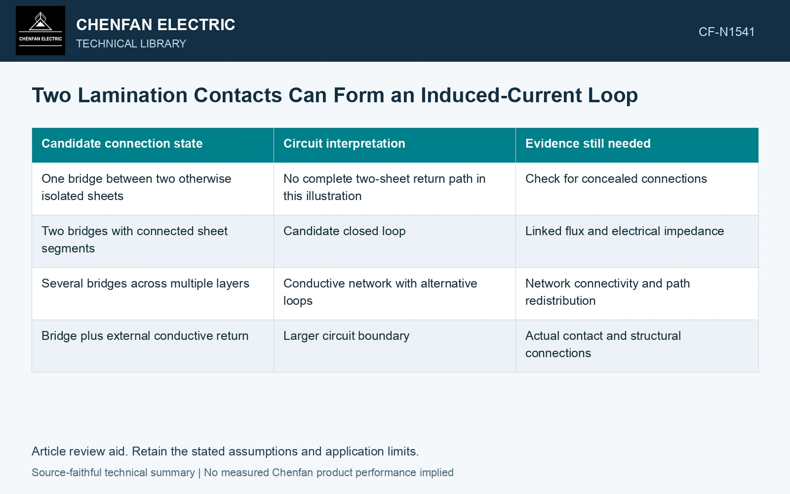
Trace the return path before measuring severity
Draw each known conductive connection and the steel segments that join it to another connection. Mark uncertain contacts separately. Include contact state under the relevant pressure; a path open in a dismantled sample may have been closed in the assembled condition.
Identify the magnetic flux linked by each candidate closed path. Induced electromotive force follows e = −dPhi/dt, where e is in volts and linked flux Phi is in webers. The loop’s geometric area matters through actual flux linkage, not merely through the distance between contacts.
| Candidate connection state | Circuit interpretation | Evidence still needed |
|---|---|---|
| One bridge between two otherwise isolated sheets | No complete two-sheet return path in this illustration | Check for concealed connections |
| Two bridges with connected sheet segments | Candidate closed loop | Linked flux and electrical impedance |
| Several bridges across multiple layers | Conductive network with alternative loops | Network connectivity and path redistribution |
| Bridge plus external conductive return | Larger circuit boundary | Actual contact and structural connections |
The drawing should remain distinct from the core-to-ground circuit. The two networks can interact in an actual construction, but they are different diagnostic questions.
Contact resistance is only one part of the loop
A narrow bridge can have a high local resistance, while the sheet segments and loop inductance also affect current. Heat generated at a contact depends on its current and electrical behavior. The largest visible bridge is not necessarily the hottest one.
Use representative electrical and thermal observations to constrain the path. Do not infer current solely from a continuity indication or calculate it by dividing induced voltage by an arbitrary contact resistance.
Move the geometry in a controlled research comparison
In a qualified laboratory investigation, varying bridge position while preserving the relevant contact construction can test the effect of changed flux linkage. Varying contact geometry while holding loop placement fixed tests a different variable. Keep those comparisons separate.
This is an experimental-design principle, not an instruction to short a production core. The laboratory specimen, excitation and containment require their own professional procedure.
The practical diagnostic output is a loop map with known, uncertain and alternative returns. It explains why finding one contact does not establish a complete fault mechanism, and why removing one visible bridge may redirect current through another path rather than eliminate every closed loop.
Technical references
- IEEJ / J-STAGE. Influence of Interlaminar Flux between Cores on Iron Loss in Three-legged Wound Transformer Core.
- FLIR. How Does Emissivity Affect Thermal Imaging?.