

A manufacturer’s fully drainable product-side design depends on that exchanger’s geometry [1]. For an idle transformer cooler, locate water retained in every pass, header and isolated branch. A drain valve at the lowest visible pipe does not demonstrate that all internal pockets empty.
Trace the water circuit in its installed orientation. Mark low points, upward loops, closed valves, headers and tube-pass details. Confirm drain and vent paths from the actual drawing and manufacturer requirements.
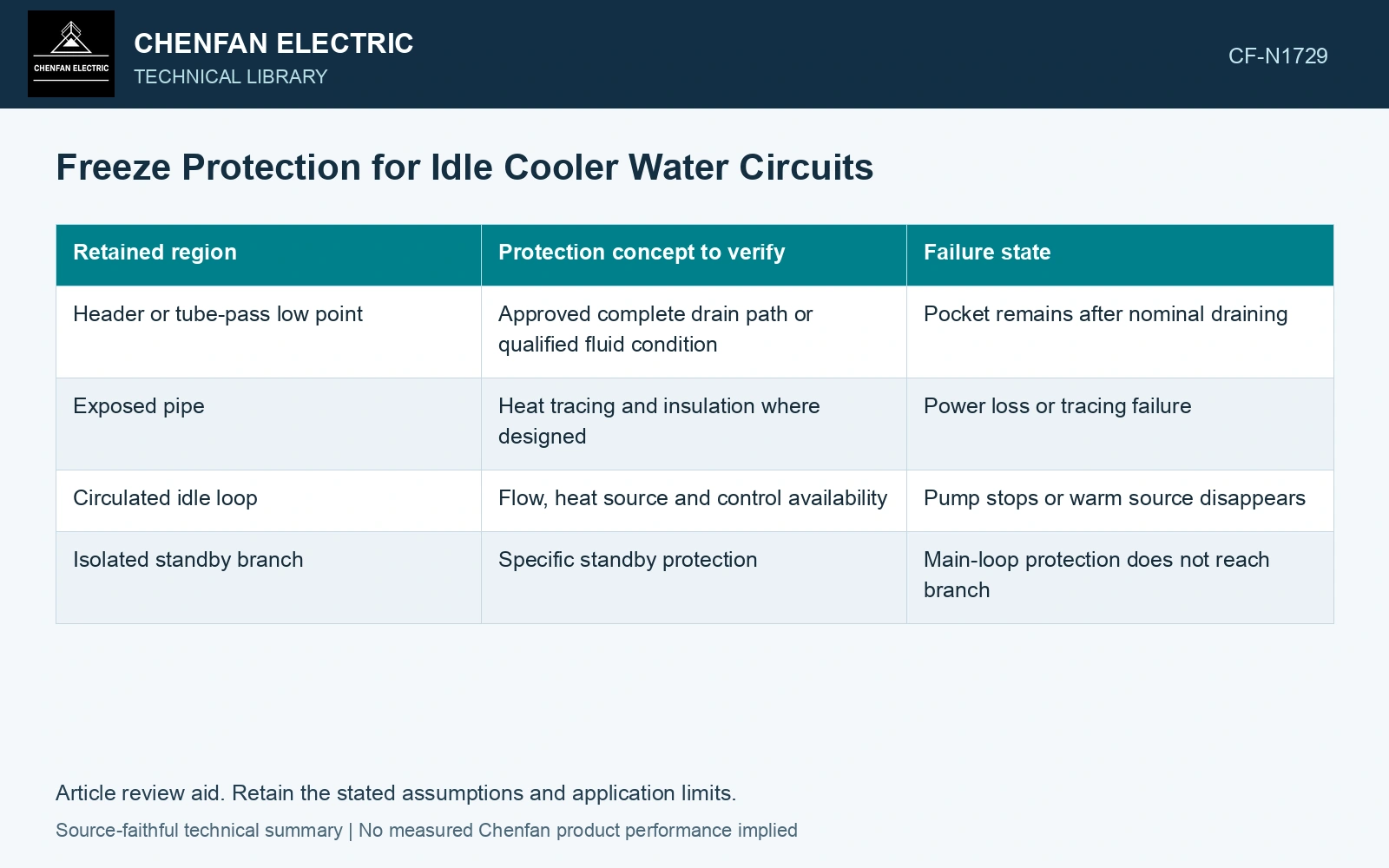
Assign protection to every retained pocket
| Retained region | Protection concept to verify | Failure state |
|---|---|---|
| Header or tube-pass low point | Approved complete drain path or qualified fluid condition | Pocket remains after nominal draining |
| Exposed pipe | Heat tracing and insulation where designed | Power loss or tracing failure |
| Circulated idle loop | Flow, heat source and control availability | Pump stops or warm source disappears |
| Isolated standby branch | Specific standby protection | Main-loop protection does not reach branch |
Test the loss-of-power premise
Heat tracing and circulation are active measures. Their assessment needs the power source, alarms and response during an outage. An idle transformer cooling loop may lose the auxiliaries assumed to protect it exactly when the plant stops.
Insulation slows heat loss but does not create heat. Its effectiveness depends on initial water temperature, exposure and time. Do not describe insulated trapped water as indefinitely freeze protected.
Use a thermal-storage balance to estimate when a retained pocket reaches the onset of freezing [2]. Insulation, heat tracing and circulation act through different terms in that balance; verify which remain available during an outage.
Estimate the onset of freezing after heat protection stops
Assume 2 kg retained water initially at 10 °C, constant specific heat 4.18 kJ/(kg·K), uniform temperature, net 100 W heat loss and negligible pipe heat capacity. Cooling to 0 °C removes 2 × 4.18 × 10 = 83.6 kJ, taking 836 s, or 13.93 min. This predicts first freezing in the lumped model, not completion of freezing or time to rupture. Local cold spots can freeze earlier; demonstrate drainage or qualified outage protection instead of using this time as an operating allowance.
Verify drainage as a state, not a label
Use the approved procedure to verify the actual emptying and venting path. Record inaccessible pockets and the measure assigned to each. Avoid improvising compressed-air pressure or chemicals from a general drainage discussion.
References
- Alfa Laval, Pharma-line Instruction Manual, ESE02198-EN, May 2012, sections 1.4, 2.5, 4.2 and 4.4.
- U.S. Department of Energy, DOE-HDBK-1012/2-92, Thermodynamics, Heat Transfer, and Fluid Flow, Volume 2, 1992.