

The primary current of an HV CT passes through its conductors and internal connections. A joint concentrates resistance in a short region. Its local temperature can therefore differ substantially from the average temperature of a long conductor or the external head. [1] [2]
ABB describes short top-core and longer hairpin primary routes [1]. Neither removes the need to evaluate the actual joint. Dong’s distribution-CT electrothermal model [2] illustrates source/heat-transfer analysis, not this HV joint’s resistance or qualified temperature.
Separate the joint contribution
For an approximately resistive joint under sinusoidal current, Pj = Irms² Rj. Power Pj is in watts, RMS current in amperes and effective joint resistance Rj in ohms at the relevant temperature and frequency. If heating changes the contact resistance, a fixed cold resistance is only a starting approximation.
Keep conductor-body loss, joint loss and induced loss in nearby metal separate. Assigning the total primary loss uniformly along the conductor can hide the very hotspot the analysis is intended to find.
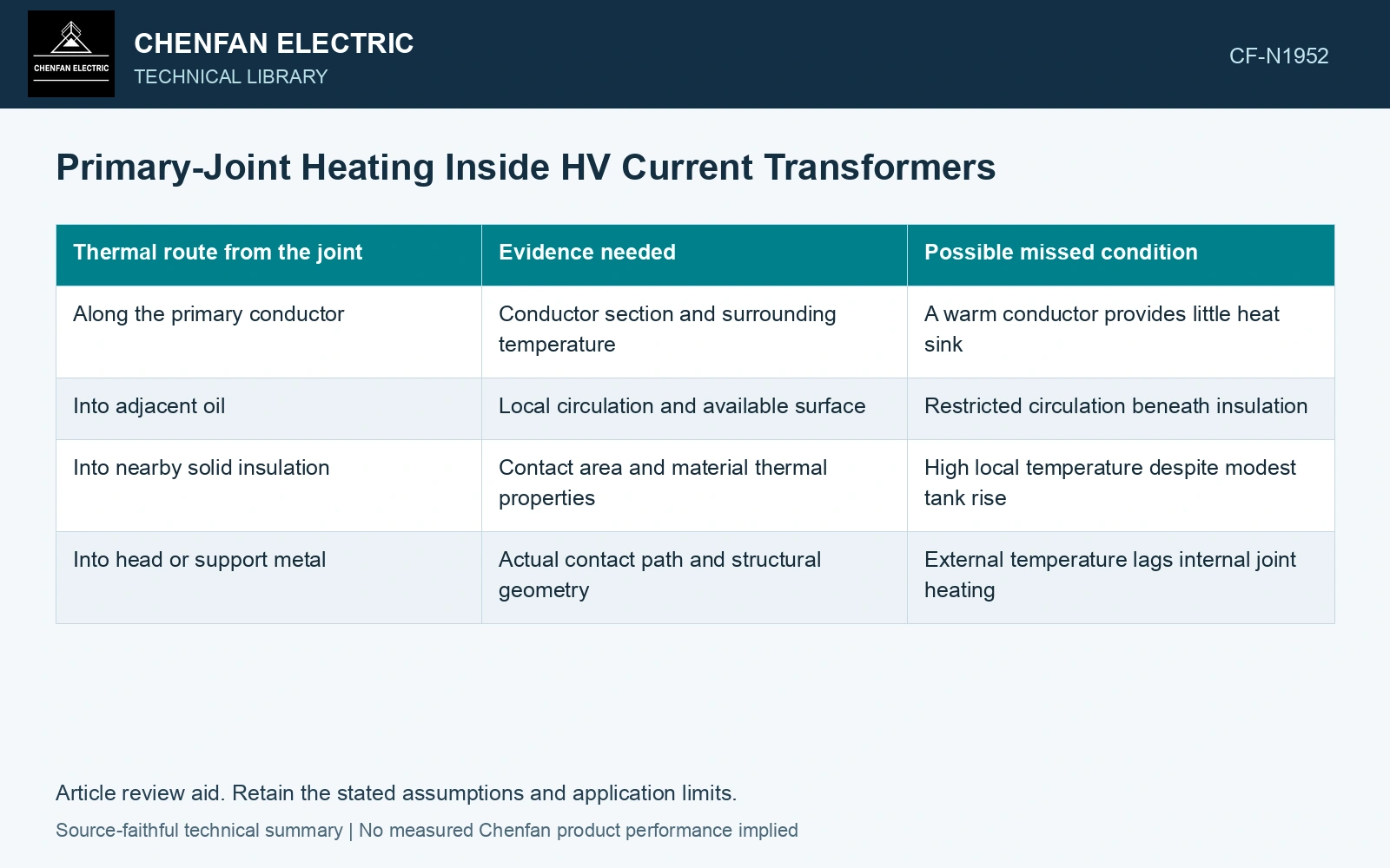
| Thermal route from the joint | Evidence needed | Possible missed condition |
|---|---|---|
| Along the primary conductor | Conductor section and surrounding temperature | A warm conductor provides little heat sink |
| Into adjacent oil | Local circulation and available surface | Restricted circulation beneath insulation |
| Into nearby solid insulation | Contact area and material thermal properties | High local temperature despite modest tank rise |
| Into head or support metal | Actual contact path and structural geometry | External temperature lags internal joint heating |
Contact condition changes the source
The connection design determines how contact pressure, surface condition and material movement affect resistance. Review the qualified assembly method and inspect the manufacturing evidence tied to the joint identity. Do not substitute a generic tightening value for the manufacturer’s contact design.
Thermal cycling can alter both contact pressure and cooling geometry. If resistance measurements are compared over time, preserve temperature correction, instrument method and measurement boundaries. A change measured across the entire primary route cannot be attributed to one joint without further evidence.
Compare the heat run with the local model
An average temperature-rise result can demonstrate a bulk thermal response while leaving the joint region weakly observed. The report should identify which measurement or validated model represents the nearby insulation temperature. A sensor location also changes what is observed: a head surface measurement may show delayed and attenuated response to an internal hotspot.
Use load duration as well as current. A short test can miss the final local thermal condition when surrounding insulation warms slowly. Conversely, transient current duties need their own time-dependent assessment.
Assume a CT joint carries 1,000 A RMS and has effective resistance 10 μΩ at the evaluated condition: I²R = 10 W. Degradation to assumed 30 μΩ gives 30 W. With assumed local Rthermal = 2 K/W [3] to the same boundary, rises are 20/60 K. Against an assumed 40 K local-rise cap, the degraded joint fails although average primary resistance may change little. Resolve actual joint contacts and cooling with a local model/measurement before applying an overall passing heat-run result.
A change in joint geometry, material or assembly method can change the local heat source or its escape path. Prior thermal evidence applies only where it still represents those features and the nearby insulation temperature. An unchanged overall CT rise cannot resolve a new internal hotspot.
References
- ABB, Instrument Transformers Application Guide, publication 1HSM 9543 40-00en, Edition 4, February 2015, sections 5.1–5.6, 6.1 and 7.1.
- B. Dong et al., Three-Dimensional Electro-Thermal Analysis of a New Type Current Transformer Design for Power Distribution Networks, Energies 14, 1792, 2021. DOI: 10.3390/en14061792.
- U.S. Department of Energy, DOE-HDBK-1012/2-92, Thermodynamics, Heat Transfer, and Fluid Flow, Volume 2, 1992.