


Transformer Core Engineering Notes · CF-N270
Transformer room ventilation should be based on heat released into the room, not on the transformer’s apparent-power rating alone. Nearby switchgear, cables, auxiliary equipment and other sources can add heat or obstruct airflow. Build a room-level heat balance for the actual operating scenarios and coordinate it with the transformer OEM’s cooling-inlet requirements.
Use losses, not delivered electrical power
Most transferred power leaves electrically, not as room heat. Build the room heat balance from the applicable transformer losses and auxiliaries that release heat inside that room. Identify any heat removed through an external cooling circuit, and avoid counting the same motor loss twice. Use operating-state loss data, not the transformer’s kVA rating. Dry-type temperature-rise and loading references must match the equipment rather than defaulting to a liquid-immersed test standard.
Add neighboring and building heat sources
Include other equipment operating in the room and identify whether its losses are already included in another allowance. Solar or building heat gains may also matter to the building-services design. Avoid double-counting the same source. For an illustrative inventory, 12 kW from a transformer plus 3 kW from neighboring equipment gives 15 kW before other room gains; these invented values are not sizing data for a real installation.
Distinguish airflow quantity from distribution
A calculated total airflow does not prove that cool air reaches the transformer inlet. Short-circuiting between room intake and exhaust, obstructions or recirculation can leave local hot regions. Review the complete flow path and pressure resistance, including louvres and filters. The ventilation designer should verify the design against the required inlet condition, rather than relying only on a fan’s free-air catalogue flow.
Evaluate operating and failure scenarios
Consider which transformers and adjacent loads can operate simultaneously, the intended ambient condition and the consequence of losing a ventilation group. A room serving redundant electrical equipment may still have a common cooling dependency. State any load restrictions following ventilation failure through the approved operating assessment. Changes in room occupancy or equipment should trigger a review of both heat load and airflow, not merely the available floor area.
| Review item | Evidence to request | Boundary to preserve |
|---|---|---|
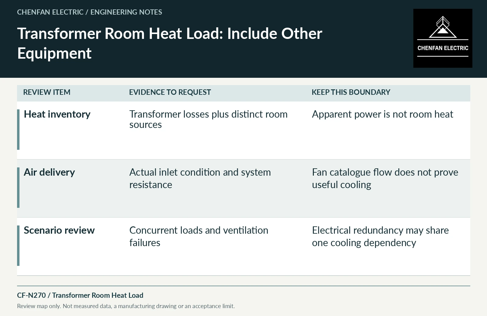
| Heat inventory | Transformer losses plus distinct room sources | Apparent power is not room heat |
| Air delivery | Actual inlet condition and system resistance | Fan catalogue flow does not prove useful cooling |
| Scenario review | Concurrent loads and ventilation failures | Electrical redundancy may share one cooling dependency |
References and scope
- IEC 60076-11:2018 — Dry-type transformersPublic standard abstract · Dry-type requirements and classification within the standard’s voltage/product scope; not a blanket reference for every LV product.
- IEC 60076-12:2008 — Loading guide for dry-type power transformersPublic standard abstract · Dry-type transformer loading, temperature and ageing scope; not a liquid-immersed loading guide.
- IEC 60076-1:2011 — Power transformers: GeneralPublic standard abstract · General transformer scope, interfaces and controlled equipment specification.