

An N+1 label does not specify a data-center transformer’s loading duty. It describes an intended redundancy relationship that must be translated into normal, one-unit-unavailable and transfer cases. The remaining transformers, buses, cables and controls must all support the proposed redistribution. A spare transformer is not effective capacity if the electrical path cannot transfer the required load.
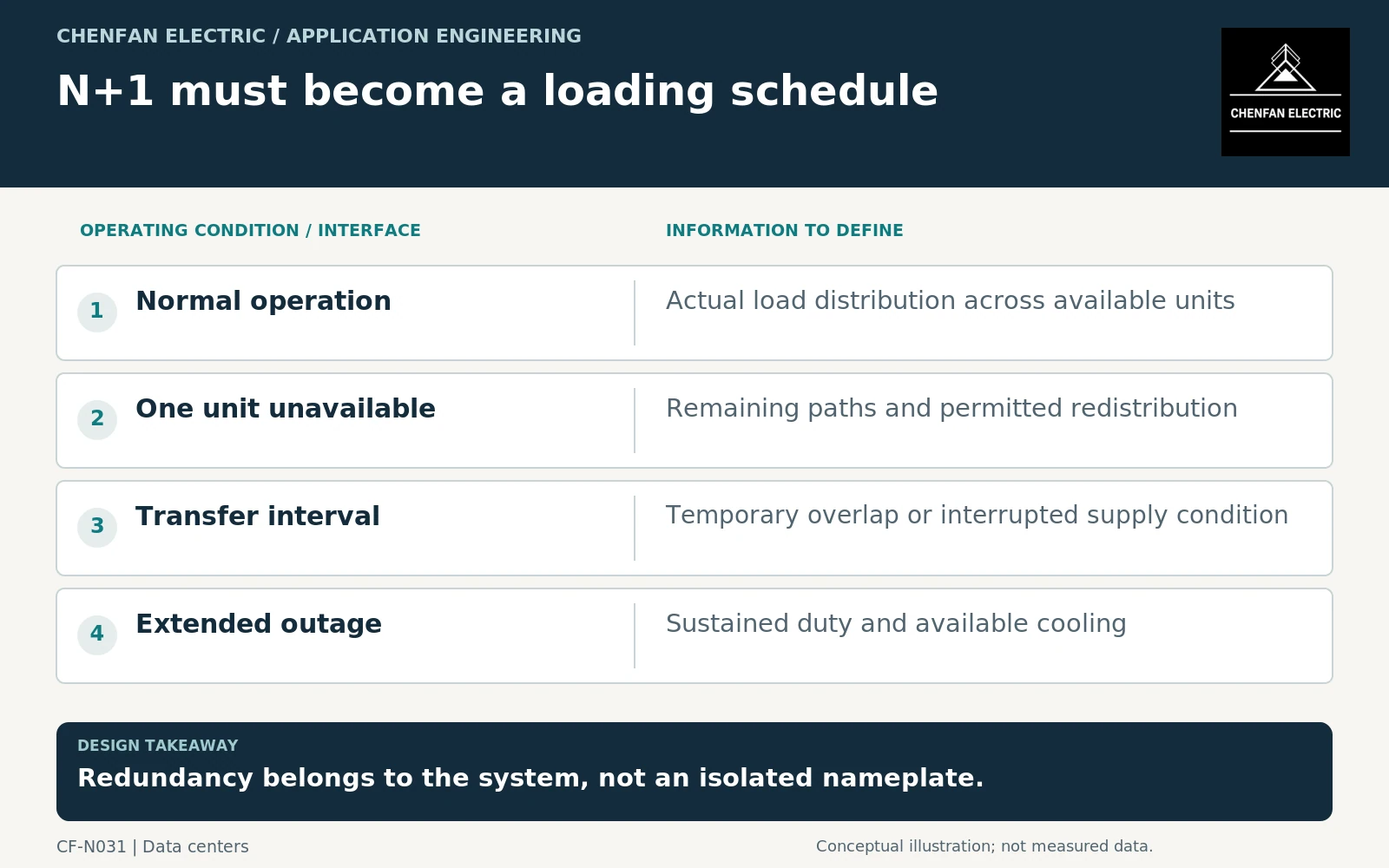
Define N at a stated demand and boundary
State the supported load, the normal operating topology and the equipment included in the redundancy claim. Distinguish information technology (IT) demand from total facility demand and identify whether the quoted transformer capacity is before or after operating restrictions.
As an illustrative arithmetic example, three transformers normally sharing 8 MVA equally each carry about 2.67 MVA. If one becomes unavailable and the full demand transfers equally, the two remaining units each carry 4 MVA. These values assume a feasible topology and equal sharing; they do not establish acceptable thermal duty, fault performance or transfer capability.
General transformer application guidance covers rating and parallel-operation considerations. The project must supply the actual availability architecture and load cases. [1]
Separate immediate transfer from extended operation
The first moments after an outage can involve switching, load pickup or re-energization, while the following hours impose a sustained thermal condition. These require different assessments. A temporary capability cannot be assumed to support an outage of indefinite duration.
Record the expected initial loading and temperature before transfer, the increased current afterward, ambient conditions and available cooling. Use the appropriate loading framework for the transformer construction. Mineral-oil and dry-type loading guides are separate and should not be interchanged without justification. [2] [3]
If load shedding is part of the design, identify the actual loads removed and the response time. An assumed reduction that is not implemented in controls or operating procedures cannot be counted as firm capacity relief.
Trace the common dependencies
| Case | Questions beyond transformer MVA |
|---|---|
| One transformer unavailable | Can the bus and cables carry redistributed current? |
| Cooling component unavailable | Is the increased duty still supported? |
| Control or communication failure | Does the transfer logic retain the intended limits? |
| Planned maintenance | Is the remaining redundancy state acceptable? |
| Extended outage | What duration and ambient assumptions remain valid? |
Review whether apparently redundant paths share switchgear, ventilation, auxiliary power or a protection zone. A common dependency can remove several units together. Naming each transformer N+1 does not eliminate that dependency.
Fault levels and protection coordination can also change when normally separated sections become connected. The transfer arrangement should be studied in its actual normal and contingency configurations rather than inferred from the number of installed transformers.
Purchase against the operating-case matrix
The enquiry should list current and duration for each transformer in every required state, including any unequal sharing. Attach the single-line diagrams and identify which cases require continuous operation and which are time-limited.
Require offers to disclose assumptions about cooling, ambient conditions and permitted overload. Do not compare one design evaluated for sustained contingency duty with another relying on a short emergency interval as though they were equivalent.
The acceptance record should connect the equipment ratings to the implemented topology and operating restrictions. N+1 becomes meaningful when the project can show what happens after a specific unit is lost, how load moves and how long the remaining equipment can support it. Until then, it is an architecture label rather than a transformer specification.
Core procurement checkpoint: Keep redundancy calculations separate from core standardization
An N+1 loading case informs the complete transformer selection. It does not alone establish that two proposed cores are interchangeable. For repeated units, use one controlled drawing only where the equipment designer has approved the same geometry and magnetic basis. Keep lot identification and inspection records linked to each delivered set so that a spare can be matched to its intended transformer design.
For the core enquiry: Approved common core drawing; number of units and spares; material specification; set identification; agreed dimensional and loss checks.