

A braided lead’s compression-lug mouth concentrates the transition from rigid barrel to flexible strands. Inspect curvature, restraint and strand movement there to distinguish entry fretting from a lug-palm contact problem. [1]
Calculation basis. Project-specific values and gates in the illustrative screens below are assumptions; cited catalogue values retain their source test conditions.
Record repeated relative contact motion where contact wear is suspected. Wear and the resulting change in current-carrying contact can matter even when the assembly has no visible gross slip. Corrosion is a separate part of the diagnosis: an oil-immersed copper braid cannot be assigned the air-exposed nickel oxidation mechanism of a plated signal connector without evidence about its actual materials and environment.
Find where flexibility becomes restraint
Draw the barrel, its mouth, the first free braid section and the nearest external support on one section. Mark which strands are compressed, which can redistribute, and where the braid first changes direction. A nearby support can reduce whole-link movement while concentrating bending into a shorter exposed length at the lug.
The same external displacement can produce different local motion with a straight entry, a tilted entry or a braid already flattened against the barrel edge. Record the installed pose and the actual support condition; a photograph of an unconstrained sample does not represent the assembled connection.
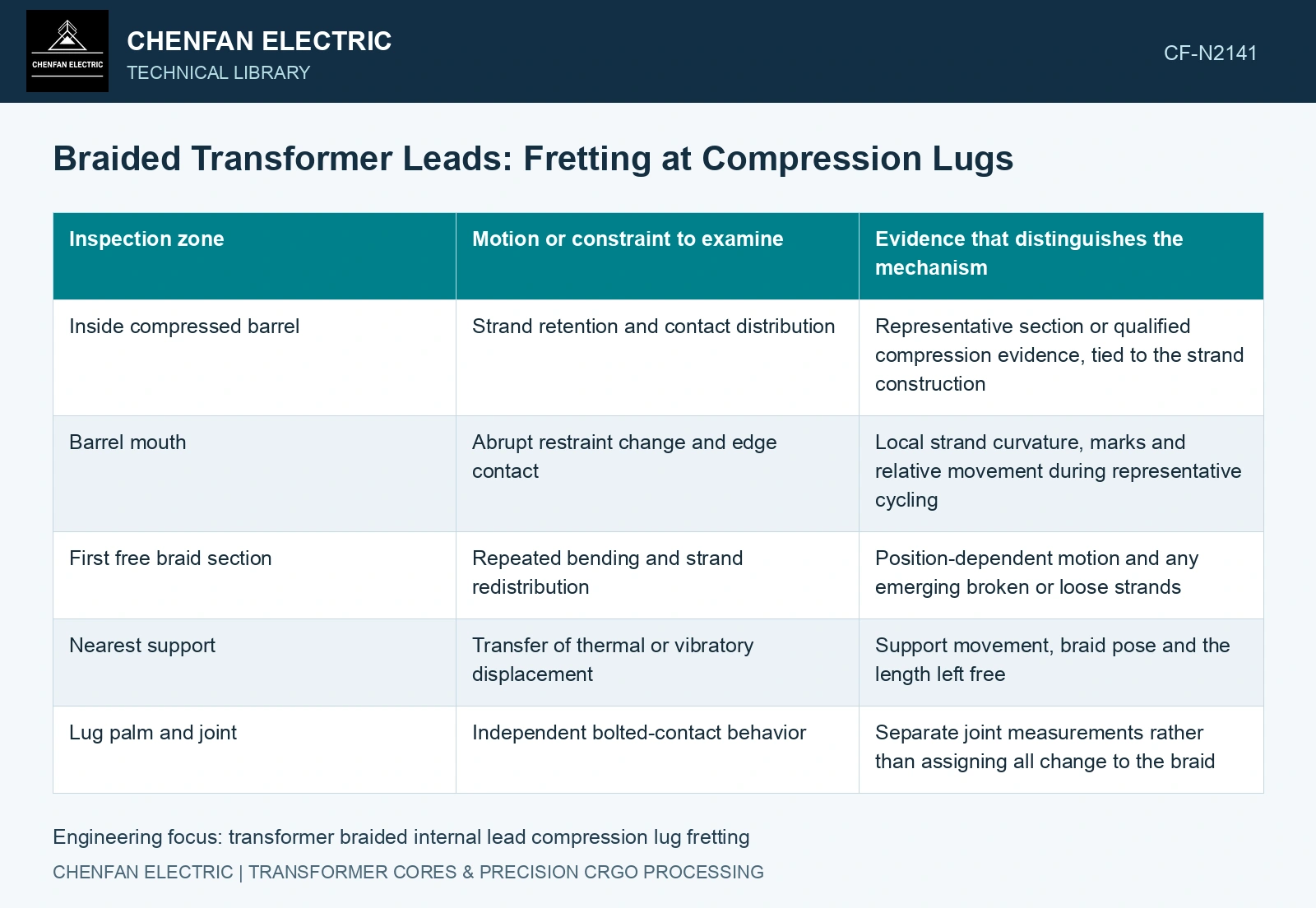
| Inspection zone | Motion or constraint to examine | Evidence that distinguishes the mechanism |
|---|---|---|
| Inside compressed barrel | Strand retention and contact distribution | Representative section or qualified compression evidence, tied to the strand construction |
| Barrel mouth | Abrupt restraint change and edge contact | Local strand curvature, marks and relative movement during representative cycling |
| First free braid section | Repeated bending and strand redistribution | Position-dependent motion and any emerging broken or loose strands |
| Nearest support | Transfer of thermal or vibratory displacement | Support movement, braid pose and the length left free |
| Lug palm and joint | Independent bolted-contact behavior | Separate joint measurements rather than assigning all change to the braid |
Use thermal movement to define the fretting test
For an illustrative straight copper segment, free expansion is ΔL = αLΔT. With α = 17 × 10⁻⁶ K⁻¹, L = 0.30 m and ΔT = 60 K, ΔL is 0.000306 m, or 0.306 mm. These assumed values show the displacement scale; they are not a transformer design allowance or a fretting amplitude.
The lug, support and opposite end can move too. Only the differential movement imposed on the flexible link is relevant to the restraint question. The braid may accommodate it through changing curvature, strand slip or several mechanisms together. A model that applies the full free expansion directly at one contact would need justification.
Correlate damage with contact stability
Compare electrical measurements at matched temperature and terminal boundaries before and after the qualified cycling history. Whole-link resistance includes the braid, compressed region and external joints. If it changes, targeted measurements or development specimens are needed to locate the contribution. An unchanged total can still conceal a local defect below the measurement’s sensitivity.
Inspect displaced contact zones before cleaning away deposits or marks. Retain their position and, where necessary, identify their composition. A dark patch alone does not establish fretting corrosion, and a broken strand can arise from concentrated bending fatigue rather than contact wear.
Correct barrel-mouth damage through entry curvature and restraint review; investigate lug-palm damage through its contact interface. Locate the mechanism before changing compression or support.
Relate lead expansion to the lug transition geometry
Joint stiffness and thermal load transfer require the actual restraint and contact geometry [2].
For the assumed 0.30 m copper segment, 17 × 10⁻⁶ K⁻¹ expansion coefficient and 60 K rise, free expansion is 0.306 mm. Assume the projected thermal mismatch imposed on this transition is 0.306 mm and it can accommodate 0.10 mm before contacting a restraint. A further 0.206 mm then requires changed braid curvature and support response in this hypothetical state; free bulk expansion alone would not establish that imposed projection. Qualify the transition under repeated thermal motion rather than using expansion alone as a fretting amplitude.
References
- U.S. Department of Energy, DOE-HDBK-1017/2-93, Material Science, Volume 2, 1993, Thermal Stress and Plant Material Problems.
- R. T. Barrett, Fastener Design Manual, NASA Reference Publication 1228, 1990.