

A metal insert transfers load through its retention interface with the composite. Qualify that complete interface at the actual temperature and electrical boundary, including the surrounding material and connection. [1]
Calculation basis. Project-specific values and gates in the illustrative screens below are assumptions; cited catalogue values retain their source test conditions.
Identify how the insert is retained: a moulded interface, adhesive route, mechanical interlock or another qualified construction. A pullout result from one retention method cannot be assigned to a different one with the same outside diameter.
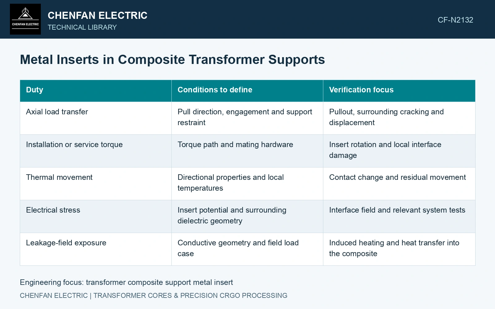
Separate the interface questions
| Duty | Conditions to define | Verification focus |
|---|---|---|
| Axial load transfer | Pull direction, engagement and support restraint | Pullout, surrounding cracking and displacement |
| Installation or service torque | Torque path and mating hardware | Insert rotation and local interface damage |
| Thermal movement | Directional properties and local temperatures | Contact change and residual movement |
| Electrical stress | Insert potential and surrounding dielectric geometry | Interface field and relevant system tests |
| Leakage-field exposure | Conductive geometry and field load case | Induced heating and heat transfer into the composite |
Do not assume the insert is at ground potential. It may be connected, floating or coupled to nearby conductors, depending on the design. Model the stated electrical arrangement; changing its connection is an insulation-design decision, not a machining correction.
Include thermal mismatch in the interface load
For an illustrative uniform-temperature comparison, take an insert diameter of 20 mm, a metal expansion coefficient of 17 × 10⁻⁶/K and a composite directional coefficient of 8 × 10⁻⁶/K. Over 60 K, their free differential diameter change is 20 × (17 − 8) × 10⁻⁶ × 60 = 0.0108 mm.
These fictional coefficients do not describe a named grade. The calculation does not determine interface pressure, stress or a permitted interference; those depend on directional stiffness, restraint, initial fit and the retention construction. A temperature gradient would require a different movement assessment.
Test representative inserts with the actual composite, processing route and relevant oil state. Pullout, rotational resistance and thermal cycling answer different questions. Inspect the surrounding material after each relevant sequence, rather than recording only the load at gross failure.
Consider installation separately. A high applied torque may damage the interface before the external fastener reaches its intended preload. Metal fastener torque tables do not provide the capacity of an insulating support’s embedded joint.
Where electromagnetic analysis identifies insert heating, use that local source in the thermal assessment. A nonmetallic outer bracket does not eliminate loss in an embedded conductive feature.
The interface qualification should identify the retention construction, mechanical load path and electrical boundary tested. An insert substitution that changes shape, material or connection needs review of the affected rows, even if its mounting thread still fits the same hardware.
Carry differential insert expansion into the fit budget
Match the material identity and relevant test direction before comparing densified-wood evidence [2]. Assess the assembled load path and fastening mechanism separately from stock properties [3].
For the assumed 20 mm insert, 17 × 10⁻⁶ K⁻¹ metal and 8 × 10⁻⁶ K⁻¹ composite directional expansion coefficients, a 60 K rise gives 0.0108 mm differential diameter growth. Against an assumed 0.020 mm initial diametral clearance, 0.0092 mm remains before moisture and tolerance contributions. For one hypothetical credible combined state, assume manufacturing variation consumes another 0.008 mm and moisture-related movement consumes 0.004 mm. Remaining clearance is −0.0028 mm, indicating interference rather than free clearance. Assess the resulting contact and dielectric interface with actual stiffness, retention geometry and correlated dimensional evidence.
References
- Röchling Industrial, Lignostone L I/2-E3-HQ (P2R), Technical Data Sheet, version 2.0, released 20 September 2023.
- IEC, IEC 61061-2:1992, Specification for non-impregnated, densified laminated wood for electrical purposes — Part 2: Methods of test.
- R. T. Barrett, Fastener Design Manual, NASA Reference Publication 1228, 1990.