

Slot ligaments carry the loads created by the part’s supports and orientation. Validate width, slot ends and loading together to define a manufacturable support layout with demonstrated mechanical coverage. [1]
Calculation basis. Project-specific values and gates in the illustrative screens below are assumptions; cited catalogue values retain their source test conditions.
Mark the load application and reaction surfaces on the drawing first. Then trace how force reaches the supports around the openings. Ventilation area is one design objective; retaining a credible mechanical path is another.
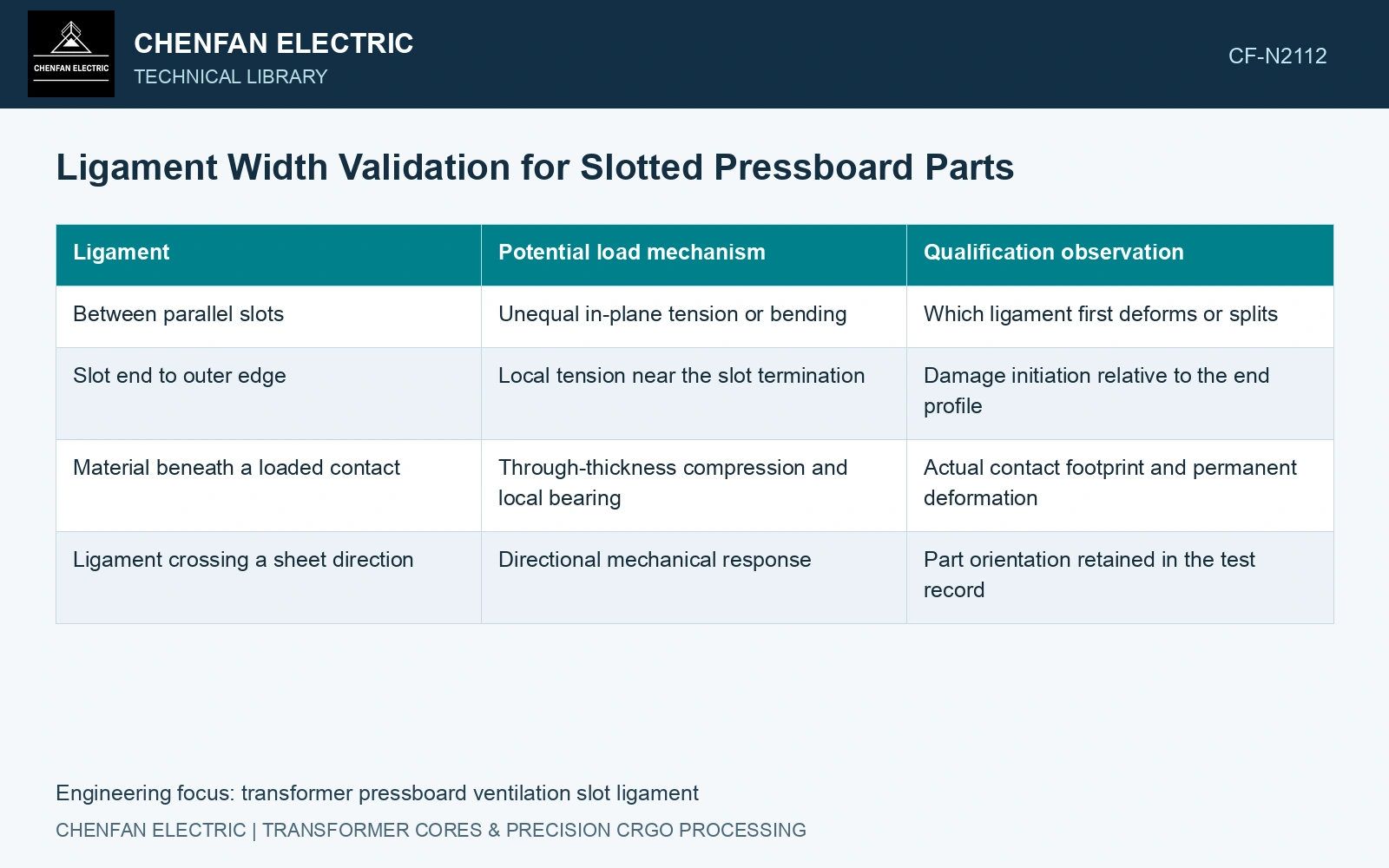
A load-path map for the remaining material
| Ligament | Potential load mechanism | Qualification observation |
|---|---|---|
| Between parallel slots | Unequal in-plane tension or bending | Which ligament first deforms or splits |
| Slot end to outer edge | Local tension near the slot termination | Damage initiation relative to the end profile |
| Material beneath a loaded contact | Through-thickness compression and local bearing | Actual contact footprint and permanent deformation |
| Ligament crossing a sheet direction | Directional mechanical response | Part orientation retained in the test record |
Use a simple net-section calculation only for the mechanism it represents. For a fictional in-plane tensile load of 300 N shared equally by two ligaments, each 5 mm wide and 3 mm thick, the total area is 30 mm². The average nominal stress is 300/30 = 10 MPa.
If one ligament instead carries 80% of that load, its nominal stress is 240/(5 × 3) = 16 MPa. Neither result includes local concentration at a slot end, damage from machining or a bending moment. These are illustrative stresses, not allowable pressboard values.
Test the actual sharing and restraint
A part fixture should reproduce the contacts that create unequal sharing. A uniformly pulled coupon may make both ligaments participate when the assembly loads only one initially. Record displacement and failure location in addition to maximum force so the assumed load path can be checked.
For a through-thickness compressed spacer, replace the tensile simplification with the actual loaded area and contact arrangement. The remaining plan area matters, but a slot under the contact can also change bending and edge support. Published MD/CD tensile values cannot be used to certify that compression duty.
Compare proposed slot lengths, spacing and termination profiles using the same material and conditioning route. A wider ligament may move the weak point to the end-to-edge region; the inspection plan must follow that change rather than examine only the original narrow strip.
Include the machined edge condition in the witnesses. Torn material or hidden layer separation can change where failure starts, even if the measured slot width is correct. The cutting-route qualification and the structural part test answer related but separate questions.
Put the validated layout and orientation range on the drawing. Revisit the mechanical map and representative tests whenever cooling development changes the slot pattern.
Check the most heavily loaded ligament
Keep conditioning, loading direction and aging state with pressboard comparisons [2].
For the assumed 300 N total load, two 5 × 3 mm ligaments give 10 MPa equal-share nominal stress. If one carries 80%, its stress is 16 MPa, 60% higher. Against an assumed 14 MPa nominal ligament allocation, equal sharing passes while the 80% path fails. Verify actual sharing, slot-root concentration and conditioned damage before accepting the layout.
References
- IEC, IEC 60641-2:2004, Pressboard and presspaper for electrical purposes — Part 2: Methods of tests.
- C. Oria, I. Carrascal, D. Ferreño, C. Méndez and A. Ortiz, Experimental dataset on the compressive mechanical properties of high-density pressboard used in power transformers spacers, Data in Brief 50, 109471, 2023. DOI: 10.1016/j.dib.2023.109471.