

Bonded pressboard blocks need oil-channel verification through their internal length. Relate accessible checks to representative sections to control adhesive squeeze-out inside the assembled block. [1]
Calculation basis. Project-specific values and gates in the illustrative screens below are assumptions; cited catalogue values retain their source test conditions.
Define three regions on the bonding drawing: the intended bond area, the region where controlled squeeze-out can occur and the channel envelope that must remain available. Applied adhesive quantity alone cannot define those boundaries after the pieces are compressed together.
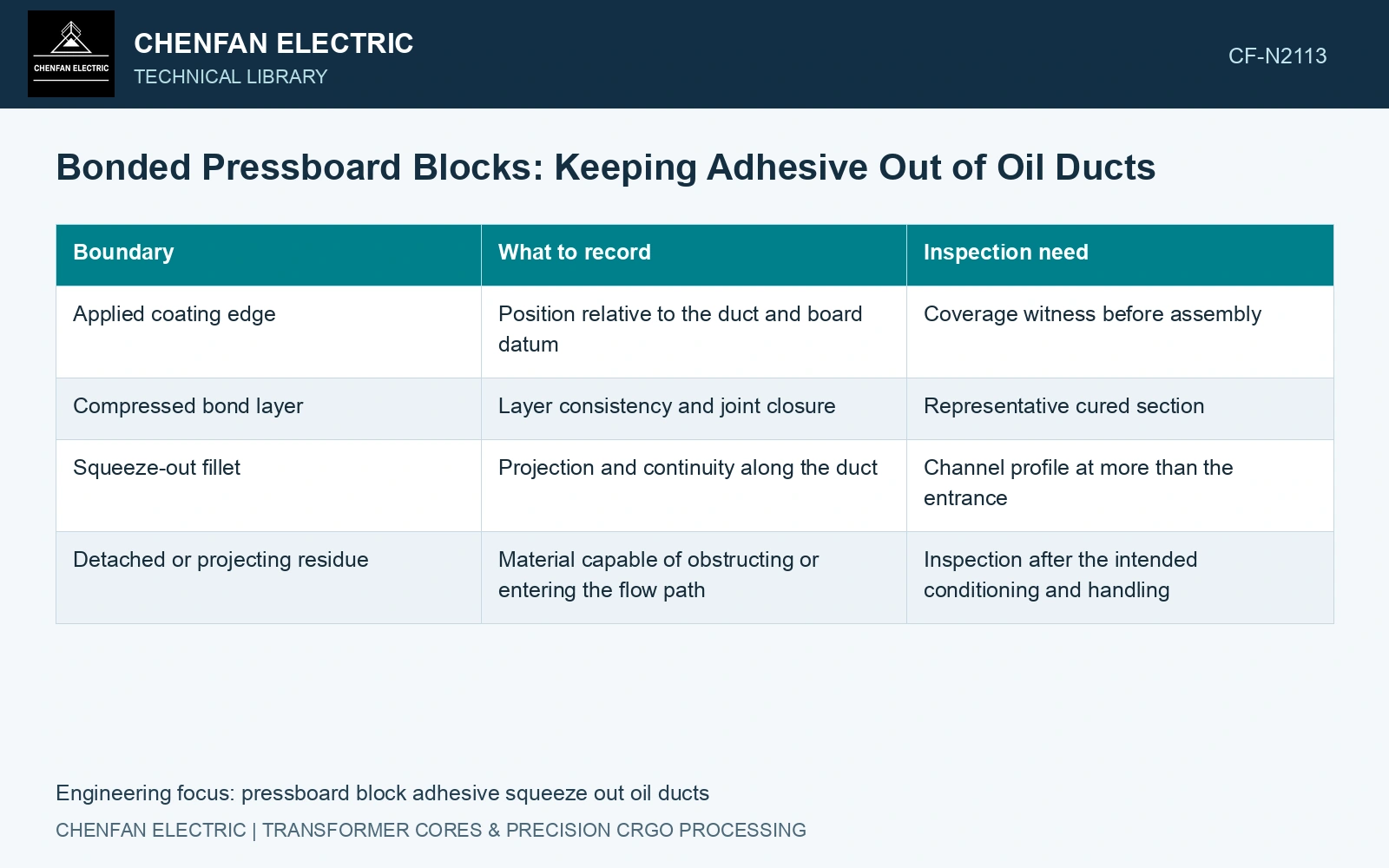
Follow the bond into the channel
| Boundary | What to record | Inspection need |
|---|---|---|
| Applied coating edge | Position relative to the duct and board datum | Coverage witness before assembly |
| Compressed bond layer | Layer consistency and joint closure | Representative cured section |
| Squeeze-out fillet | Projection and continuity along the duct | Channel profile at more than the entrance |
| Detached or projecting residue | Material capable of obstructing or entering the flow path | Inspection after the intended conditioning and handling |
A local area calculation helps describe a section but does not qualify its hydraulics. In a fictional rectangular channel 8 mm wide and 4 mm high, the nominal area is 32 mm². Two triangular fillets, each with 1 mm legs, occupy 0.5 mm² each, leaving 31 mm² at that section.
Those illustrative dimensions say nothing about a blockage further downstream, a different fillet profile or pressure loss. A long narrow projection can change the wetted geometry and create a more severe restriction than its area fraction suggests.
Inspect after the shape has formed
Qualification blocks should represent the proposed material, adhesive route, layer geometry and assembly restraint. Section witnesses at locations likely to accumulate squeeze-out, including duct intersections and closed ends. A section remote from the duct cannot establish the channel condition.
Examine the cured channel before and after the intended drying or impregnation sequence where relevant. Identify whether an observed deposit is attached adhesive, a loose fragment or board fiber; the correction depends on the material and transfer mechanism.
Qualify the actual construction material and insulating-liquid contact system [2]. A laminate designation cannot establish compatibility or bond durability for another adhesive-built block. Obtain material-specific evidence for the electrical duty, oil exposure and processing state without assuming that “for transformers” covers every joint.
Check mechanical bonding and channel geometry separately. Reducing coating to prevent squeeze-out can leave incomplete bonding; increasing assembly pressure can close the joint while forcing more material into the duct. Compare both outcomes in the same qualification specimens.
Use accessible channel checks validated by sections. Define representative internal witnesses and their coverage where a long bonded passage remains hidden from routine inspection.
Keep adhesive fillets in the hydraulic section model
Continuity relates the actual section area to velocity at the assumed flow [3].
The assumed 8 × 4 mm duct has 32 mm² nominal area. Two triangular 1 mm-leg fillets remove 1 mm², leaving 31 mm², a 3.125% area reduction. At an assumed unchanged 10 mL/s flow, mean section velocity rises from 0.3125 to 0.3226 m/s. Assume a hidden duct intersection instead has two 2 mm-leg triangular fillets. It leaves 28 mm² and gives 0.3571 m/s at the same imposed flow. Against an assumed 30 mm² minimum-open-section drawing requirement, the first section passes and the hidden throat fails. Inspect the full internal route and verify resistance; visible entrance area alone cannot establish the duct.
References
- IEC, IEC 60641-2:2004, Pressboard and presspaper for electrical purposes — Part 2: Methods of tests.
- IEC, IEC 63177:2024, Test methods for compatibility of construction materials with electrical insulating liquids.
- U.S. Department of Energy, DOE-HDBK-1012/3-92, Thermodynamics, Heat Transfer, and Fluid Flow, Volume 3, 1992.