

Dust capture and finished pressboard cleanliness are separate production results. Use transfer witnesses from cutter to packing to locate where residue reaches the part and verify the effective correction.
Calculation basis. Project-specific values and gates in the illustrative screens below are assumptions; cited catalogue values retain their source test conditions.
Start with a dust-transfer map for the actual station. Follow the path from the cut to the finished part, including the surfaces that contact it after machining. A clean-looking cutting zone is not the final boundary of the route.
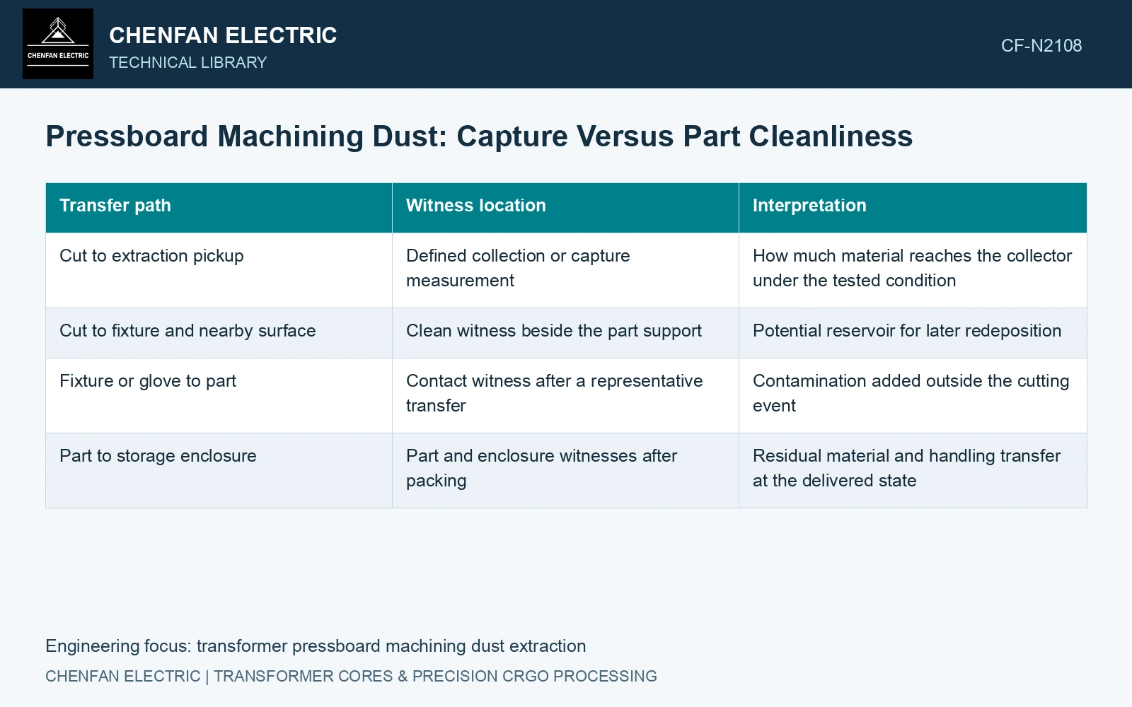
| Transfer path | Witness location | Interpretation |
|---|---|---|
| Cut to extraction pickup | Defined collection or capture measurement | How much material reaches the collector under the tested condition |
| Cut to fixture and nearby surface | Clean witness beside the part support | Potential reservoir for later redeposition |
| Fixture or glove to part | Contact witness after a representative transfer | Contamination added outside the cutting event |
| Part to storage enclosure | Part and enclosure witnesses after packing | Residual material and handling transfer at the delivered state |
Keep the measurement boundaries visible
Keep the mass-conservation accounting boundary explicit [1]. In an illustrative mass balance, 20 g of generated debris and 18 g reaching the collector would indicate 90% mass capture under that measurement definition. The remaining 2 g could be on the machine, on parts, suspended locally or elsewhere. It cannot all be assigned to the parts, and it cannot be assumed harmless because the capture percentage is high.
A valid capture measurement needs an appropriate way to establish generated and collected quantities. Fine material, moisture changes and material left inside ducts or the machine can affect a simple weighing comparison. Keep those limitations separate from the part-residue inspection.
For product cleanliness, use a defined part area or geometry and a validated collection method. Report residue by the chosen categories, including fibers and any foreign material. Include blank witnesses through the same handling and measurement steps so residue from the sampling medium is not attributed to machining.
Check cleanup and the next operation
Compare parts immediately after machining, after the proposed cleanup and after a representative handling sequence. A lower residue result following cleanup can be lost when the part returns to a dusty fixture. Conversely, an aggressive cleanup method can improve residue while damaging the profile.
Change one relevant condition at a time when comparing extraction arrangements: part location, tool engagement, pickup geometry or the cleanliness of contact surfaces. Record the actual operating state so the result can be associated with a reproducible setup.
The starting sheet’s manufacturer cleanliness statement does not cover dust introduced by conversion. Nor does a cleanliness witness qualify a ventilation system or establish combustible-dust safety; those require the relevant specialist design and controls.
A useful production response names the contaminated transfer point. If residue appears only after packing, increasing capture at the cutter may accomplish little. Correct the fixture, handling or enclosure route that the witnesses identify, then verify the part at the point where it leaves that route.
Judge the delivered part using its own residue measurement
Keep the assumed 20 g generated, 18 g collected and 2 g elsewhere. Assume a defined part wash recovers 0.20 g, with full recovery established for this demonstration. This represents 1% of generated mass and 10% of uncollected mass. The other 1.80 g remains in different sinks.
Assume the part-residue estimate has a ±0.02 g comparison interval including blank and recovery effects [2], and the project permits at most 0.15 g for this defined part and method. Even the 0.18 g lower endpoint fails. Correct the identified transfer route and repeat the delivered-part check; 90% collector capture cannot release the part.
References
- U.S. Department of Energy, DOE-HDBK-1012/3-92, Thermodynamics, Heat Transfer, and Fluid Flow, Volume 3, 1992.
- B. N. Taylor and C. E. Kuyatt, NIST Technical Note 1297, Guidelines for Evaluating and Expressing the Uncertainty of NIST Measurement Results, 1994, sections 5 and 6.