

An isolated magnetic-shunt pack needs an explicit electrical connection map. The structural-loss review describes circulating currents through mechanical connections; apply that concern to the actual packet, support and tank nodes. [1]
Identify the actual electrical nodes
Name the tank, packet, support and intentional bond nodes. Determine which surfaces have real conductive continuity. Insulated laminations or subsections need separate nodes; bonding one exposed sheet does not automatically connect every section.
Record possible capacitive coupling and the paths linked by time-varying magnetic flux where relevant. “Floating” identifies the absence of a defined conductive reference path; it does not mean that the node has no induced potential or electromagnetic interaction.
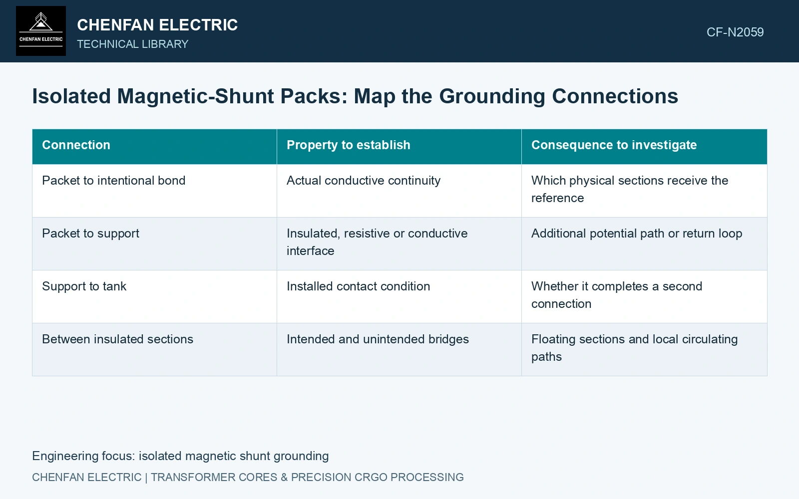
| Connection | Property to establish | Consequence to investigate |
|---|---|---|
| Packet to intentional bond | Actual conductive continuity | Which physical sections receive the reference |
| Packet to support | Insulated, resistive or conductive interface | Additional potential path or return loop |
| Support to tank | Installed contact condition | Whether it completes a second connection |
| Between insulated sections | Intended and unintended bridges | Floating sections and local circulating paths |
Trace a second path before calling it a loop
For example, an intentional packet-to-tank bond and a separate packet-to-support-to-tank connection can form a conductive circuit. Its significance depends on the magnetic flux linked by that circuit, resistance and geometry. A single-point connection concept can avoid some large return paths, but it does not remove currents within a sheet or every interlaminar bridge.
Assess the as-built interfaces after mounting. Coating, oxide, pressure and unintended contact can make actual connectivity differ from the drawing. Use the specified continuity and insulation verification methods; no generic acceptance value applies solely because the component is a shunt.
Keep the numerical reference distinct
A ground or reference-potential condition may be needed to solve a numerical electrical model. It must represent the intended physical connection where that connection affects the result. Adding an arbitrary ground for solver convenience does not establish a safe or correct bonding construction.
Magnetic permeability, electrical conductivity and interface continuity are separate model inputs. A numerically convenient reference potential cannot establish that an installed conductive bond exists.
Assume a shunt pack has one intended earth connection of 0.10 Ω and a second contact through a fastener of 0.20 Ω. With assumed induced loop voltage 0.30 V RMS and negligible reactance, I = 0.30/0.30 = 1.0 A and I²R = 0.30 W [2]. A reading at the intended terminal alone cannot identify the second path. Inspect both contacts and verify isolation in the approved de-energised configuration. Remove the unintended loop while preserving the specified protective connection.
Review the intentional reference, floating sections and additional conductive paths against the transformer requirements. Keep potential control and conductive-loop risk visible on the same node map.
References
- S. Mikulić and D. Žarko, Stray Losses in Structural Components of Power Transformers, Energies 19, 322, 2026, sections 3.1 and 3.5. DOI: 10.3390/en19020322.
- U.S. Department of Energy, DOE-HDBK-1011/4-92, Electrical Science, Volume 4, 1992.