

Copper-shield thickness sets the induced-current distribution alongside frequency, plate geometry and return paths. Use skin depth as a scaling parameter, then evaluate shielding, copper loss and local temperature together. [1]
Calculate the penetration scale
For a linear good conductor, skin depth is δ = √[2/(ωμσ)], with ω = 2πf, permeability μ and conductivity σ. This conducting-medium scale is also used in the harmonic bushing-region analysis [1]; it does not itself solve a finite copper shield.
Using illustrative assumptions σ = 58 × 10⁶ S/m and μ = μ0 = 4π × 10⁻⁷ H/m gives δ ≈ 9.35 mm at 50 Hz and 2.96 mm at 500 Hz. These are calculated scales, not measured material properties or recommended shield thicknesses. Conductivity at the relevant temperature belongs in the actual calculation.
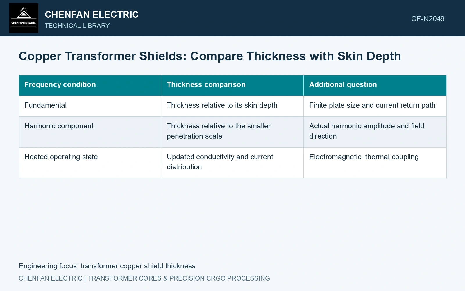
| Frequency condition | Thickness comparison | Additional question |
|---|---|---|
| Fundamental | Thickness relative to its skin depth | Finite plate size and current return path |
| Harmonic component | Thickness relative to the smaller penetration scale | Actual harmonic amplitude and field direction |
| Heated operating state | Updated conductivity and current distribution | Electromagnetic–thermal coupling |
Evaluate attenuation with the complete shield geometry
A finite shield has edges, cutouts and nearby conductive structures. Its field reduction depends on induced-current loops and coupling to the source. A plate thinner than one skin depth can still influence the field, while a thick plate with interrupted current paths may perform differently from an infinite slab.
A finite-thickness solution or a justified approximation must resolve the relevant penetration and current paths. Check the chosen approximation against a resolved geometry over the required frequency and temperature range.
Count the copper’s loss
Integrate the appropriate resistive-loss density using a consistent waveform or phasor convention. Inspect edge and connection concentrations, not only total shield power. Include this spatial heat source in the thermal model with actual oil access and mounting conduction.
Retain the source spectrum. A fundamental-frequency result cannot establish performance under harmonic current, and nonlinear magnetic parts can complicate independent harmonic superposition. Use the model appropriate to those conditions rather than adding unrelated attenuation percentages.
For an assumed 3 mm copper plate, the stated linear skin-depth calculation gives thickness/δ = 0.321 at 50 Hz and 1.015 at 500 Hz. That tenfold frequency change therefore takes the same plate from well below one skin depth to approximately one skin depth. It does not establish adequate attenuation or acceptable heat. Compare the actual harmonic field, plate edges and electrical contacts before choosing a thicker plate; moving a local field away from the wall can transfer loss into the copper itself.
The structural-loss review distinguishes conductive shields from magnetic shunts and includes the shield’s own heat in the loss balance [2]. Choose thickness against tank plus copper losses and governing local temperatures, not the field attenuation alone.
References
- S. Khan et al., Computation of Stray Losses in Transformer Bushing Regions Considering Harmonics in the Load Current, Applied Sciences 10, 3527, 2020. DOI: 10.3390/app10103527.
- S. Mikulić and D. Žarko, Stray Losses in Structural Components of Power Transformers, Energies 19, 322, 2026, sections 3.1 and 3.5. DOI: 10.3390/en19020322.