

Contact witnesses locate particle transfer from the gripper to GOES. Compare source-stack, tool and environmental contributions, then use the same registered evidence to verify the cleaning intervention.
Map the contacts
Record suction lips, support pads, stops and other surfaces that touch the steel. Add contact pressure or vacuum state, dwell and sliding where they occur. Inspect these locations for retained debris, wear products or residues. A tool can be visually clean overall while a narrow contact edge retains particles.
Use suitable clean witness surfaces or representative sacrificial laminations with a documented initial condition. Register the contact locations so that the after-image can be compared with the before-image. The witness material and preparation must not introduce a new transfer mechanism that is absent on production steel.
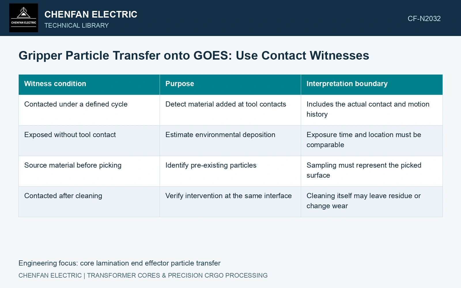
| Witness condition | Purpose | Interpretation boundary |
|---|---|---|
| Contacted under a defined cycle | Detect material added at tool contacts | Includes the actual contact and motion history |
| Exposed without tool contact | Estimate environmental deposition | Exposure time and location must be comparable |
| Source material before picking | Identify pre-existing particles | Sampling must represent the picked surface |
| Contacted after cleaning | Verify intervention at the same interface | Cleaning itself may leave residue or change wear |
Compare the spatial evidence
Repeated spatial clusters matching a contact support investigation of that interface, while random deposition suggests another source. Colour and outline do not establish composition; conductive steel, coating flakes and polymer wear require different analyses.
Retain particle counts or size classes only within a defined inspected area and detection resolution. Changing magnification or lighting between before and after images can create an apparent cleaning improvement. A negative observation means no detected transfer within the method’s sensitivity.
Verify the cleaned contact under use
After a defined cleaning method, repeat the same witness cycle and then include representative repeated contacts. If transfer returns quickly, inspect wear or particle capture rather than simply increasing cleaning frequency. Confirm that the cleaning route is compatible with the contact material and steel coating.
Contact pressure, residual suction, wear and electrostatic attraction are candidate mechanisms. A witness pattern can guide isolation trials; it does not by itself establish which mechanism or contaminant is responsible.
Assume independent Poisson counts in four matched 20 cm² images of 0.23 mm catalogue-gauge GOES [1]: contacted before/after 4/16; non-contact before/after 3/7. Contact-associated increment is [(16−4)−(7−3)]/20 = 0.40 particles/cm². Standard uncertainty is √(16+4+7+3)/20 = 0.274 particles/cm²; a stated ±2u interval is −0.148 to +0.948 [2]. This single comparison does not resolve positive enrichment. Repeat controlled paired witnesses with fixed imaging threshold before crediting cleaning or assigning the source. Record size/composition separately; a hypothetical 20 μm fragment is 8.7% of one nominal 230 μm sheet gauge, not a short-circuit threshold.
Pad material, wear state, cleaning residue and handling sequence control particle transfer. Check coating integrity and deposited material separately; a clean-looking tool can still introduce conductive or abrasive debris.
Close the investigation with the mapped source, measured transfer change and affected material condition. A cleaning log documents an action. The witness comparison establishes whether that action changed the contamination pathway.
References
- Nippon Steel Corporation, Grain-Oriented Electrical Steel Sheets, catalogue D004je, April 2020, specification and typical-property tables.
- B. N. Taylor and C. E. Kuyatt, NIST Technical Note 1297, Guidelines for Evaluating and Expressing the Uncertainty of NIST Measurement Results, 1994, sections 5 and 6.