

GOES coating qualification combines registered surface features with electrical insulation measurements. Classify laser-track morphology and measure the corresponding coating function before deciding how a visible feature affects acceptance. [1] [2]
Describe the feature before judging it
Use registered microscopy to distinguish a shallow groove, a change in surface contrast, a discontinuity within the coating and exposed substrate. Record whether a suspected crack runs along the track, crosses it or extends beyond it. Illumination and viewing angle can change the appearance of a groove, so retain the imaging conditions and a corresponding untreated surface.
Where a section is necessary, identify how it was prepared. Mounting, polishing and sectioning can introduce damage or smear a thin coating. Several sections at known positions are more informative than one image chosen because it looks severe. The observation should report what can actually be resolved at that scale.
Pair morphology with an electrical response
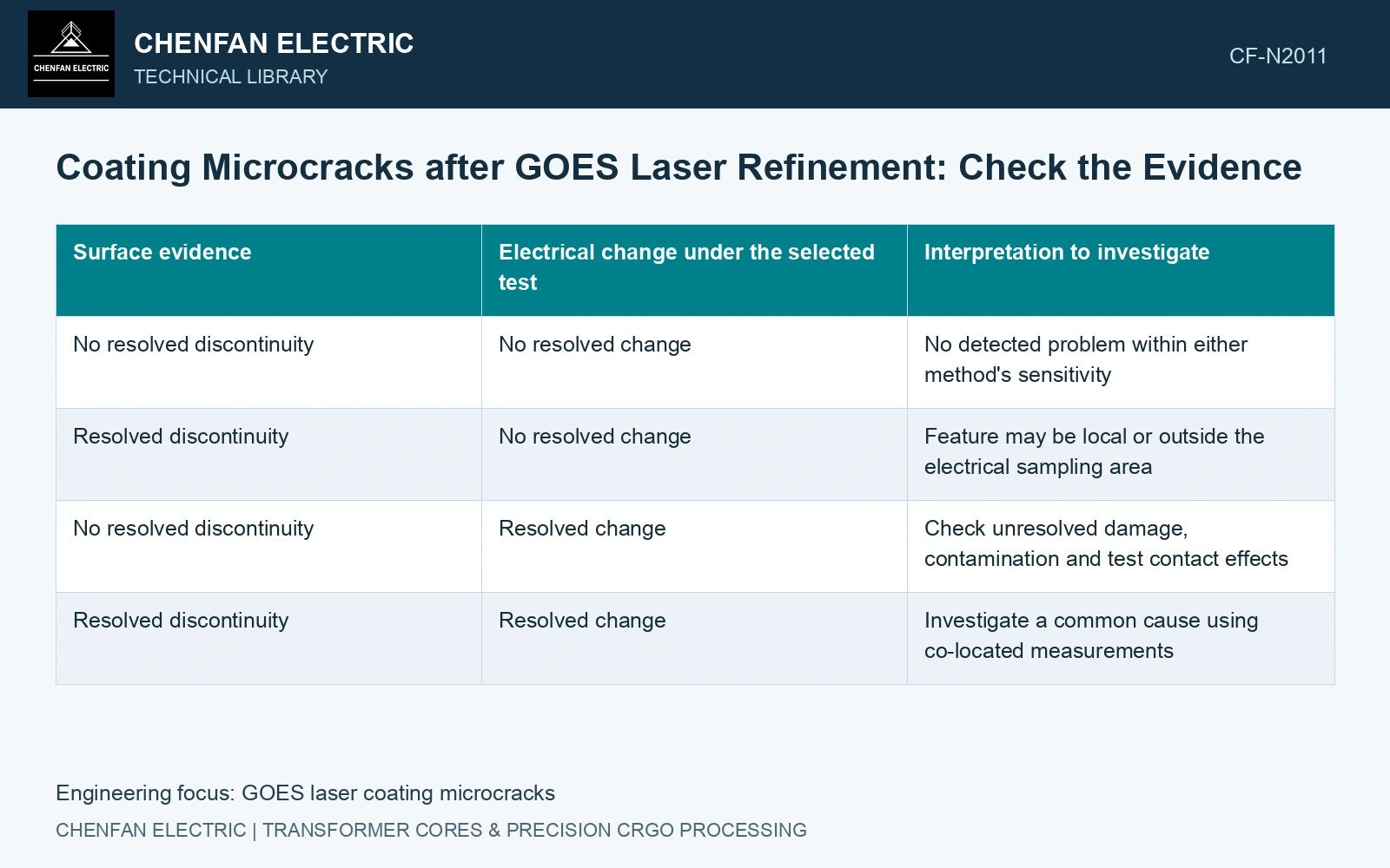
| Surface evidence | Electrical change under the selected test | Interpretation to investigate |
|---|---|---|
| No resolved discontinuity | No resolved change | No detected problem within either method’s sensitivity |
| Resolved discontinuity | No resolved change | Feature may be local or outside the electrical sampling area |
| No resolved discontinuity | Resolved change | Check unresolved damage, contamination and test contact effects |
| Resolved discontinuity | Resolved change | Investigate a common cause using co-located measurements |
“No resolved change” means no change distinguishable by the method and its uncertainty; it does not mean perfect insulation. A large electrode area can average a narrow damaged line with intact coating. Contact pressure, electrode condition and surface contamination can also alter the result. Compare like conditions and record whether the electrical measurement actually crosses the suspected feature.
Connect the observation to the stack
A coating defect matters through its position and contact conditions in the assembled laminations. Opposing surfaces, local pressure, burrs and conductive debris affect whether an electrical bridge forms. A crack image alone cannot establish the current path or quantify a core-loss penalty.
Primary laser-scribing research reports coating damage under some treatment conditions and changes in magnetic response. That supports checking the surface as part of process qualification. It does not supply a universal crack-size acceptance limit or an electrical-failure threshold for every coating system.
Catalogue gauge is 0.23 mm = 230 μm [3]. An assumed 20 μm-deep feature is 8.70% of steel thickness, which does not establish an electrical bridge. In a separate non-standard teaching DC check at fixed voltage/contact pressure, assumed resistance 100→20 Ω raises current fivefold. These are not IEC 60404-11 procedure values or limits [2]. Hold that process indication for co-located morphology/electrical investigation under the agreed method; appearance and mean magnetic loss cannot resolve the current path.
Track energy, focus, coating condition and handling contamination govern crack formation and bridging. Retain the as-processed witness and inspect both faces before attributing a changed stack result to magnetic domain refinement alone.
Report the morphology class, inspected area, electrical sampling area and stack condition together. If a surface indication and an electrical change occur at the same registered location, investigate that process condition. If they disagree, resolve the sampling mismatch before rejecting or accepting the material on appearance alone.
References
- P. Rauscher et al., The influence of laser scribing on magnetic domain formation in grain oriented electrical steel visualized by directional neutron dark-field imaging, Scientific Reports 6, 38307, 2016, Table 1. DOI: 10.1038/srep38307.
- IEC, IEC 60404-11:2021, Magnetic materials — Part 11: Methods of measurement of the surface insulation resistance of electrical steel strip and sheet.
- Nippon Steel Corporation, Grain-Oriented Electrical Steel Sheets, catalogue D004je, April 2020, specification and typical-property tables.