

Identify the actual sealed instrument-transformer expansion arrangement. ABB describes a quartz-filled option avoiding moving bellows/membranes [1]; where bellows are fitted, assess usable compensation volume and the reference position rather than total catalogue travel.
Lee et al. study oil expansion coupled with structure in a hermetically sealed power transformer [2], not this instrument-transformer bellows. Hot expansion and cold contraction consume opposite reserves; use the unit manufacturer’s actual volume/position and pressure relation.
Calculate the volume demand first
For a first-order model with constant properties, oil expansion is ΔVo = βo Vo ΔTo. Oil volume Vo and expansion ΔVo are in m³, volumetric expansion coefficient βo is in K⁻¹, and oil temperature change ΔTo is in kelvin. Use a temperature-dependent property model when the range makes the constant approximation inadequate.
The enclosure also expands. Subtract its available-volume increase from the oil expansion to estimate net compensation demand, while retaining any other compliant volumes or gas spaces actually present. Using the oil volume alone can overstate demand; assuming an unverified gas cushion can understate it.
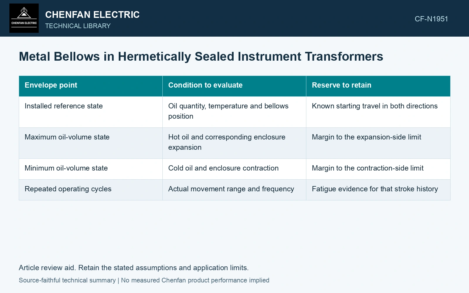
| Envelope point | Condition to evaluate | Reserve to retain |
|---|---|---|
| Installed reference state | Oil quantity, temperature and bellows position | Known starting travel in both directions |
| Maximum oil-volume state | Hot oil and corresponding enclosure expansion | Margin to the expansion-side limit |
| Minimum oil-volume state | Cold oil and enclosure contraction | Margin to the contraction-side limit |
| Repeated operating cycles | Actual movement range and frequency | Fatigue evidence for that stroke history |
Translate volume into movement with the real geometry
In an ideal constant-effective-area volume ledger, Δx = ΔVnet/Aeff, with m³/m² giving metres [3]. Variable-area bellows require the actual V(x) curve, plus pressure/force compatibility; geometry alone supplies no stiffness or fatigue life.
Record the installed position with its temperature and measurement convention. An oil-level indication and a bellows-position indication may be related, but they are not identical measurements unless the design establishes that relation.
Separate reaching a stop from cyclic damage
Operating within the travel limits does not by itself establish fatigue life. Many small cycles and occasional large cycles create different motion histories. Review the qualified cyclic envelope, including temperature excursions expected during storage or outages where relevant.
Assume oil volume 0.020 m³, constant volumetric expansion coefficient 7 × 10⁻⁴ K⁻¹ and a 60 K oil-temperature rise. Oil expansion is 0.00084 m³, or 0.84 L. If net expansion is fully assigned to a bellows with assumed constant effective area 0.010 m², required stroke is 84 mm. Against an assumed usable stroke of 70 mm, the model is short by 14 mm. Reconcile tank expansion, gas space and the manufacturer’s actual volume–stroke curve before changing the fill setting.
A position trend that moves progressively at the same reference temperature deserves investigation. Oil inventory changes, altered pressure conditions or mechanical changes can all shift it; a single displaced reading does not identify the cause. The final envelope should show the installed point, both temperature extremes and the qualified movement history, making unavailable stroke visible before it becomes an operating limitation.
References
- ABB, Instrument Transformers Application Guide, publication 1HSM 9543 40-00en, Edition 4, February 2015, sections 5.1–5.6, 6.1 and 7.1.
- S. Lee, J. Y. Lee, J. C. Yun, J. Y. Park and J. H. Woo, Development of Thermal and Structural Design Technology for a Hermetically Sealed Oil Transformer, WIT Transactions on the Built Environment 126, 2012. DOI: 10.2495/SU120161.
- U.S. Department of Energy, DOE-HDBK-1012/3-92, Thermodynamics, Heat Transfer, and Fluid Flow, Volume 3, 1992.