

The old NGR needs replacement. Since its installation, the site has added feeders, variable-speed drives, filters and a new bus-coupler mode. An identical replacement can match the original component while serving a materially different network. [1]
Use the old nameplate as historical evidence, then establish the present system. The replacement decision should carry that updated network through grounding, protection, thermal duty and monitoring.
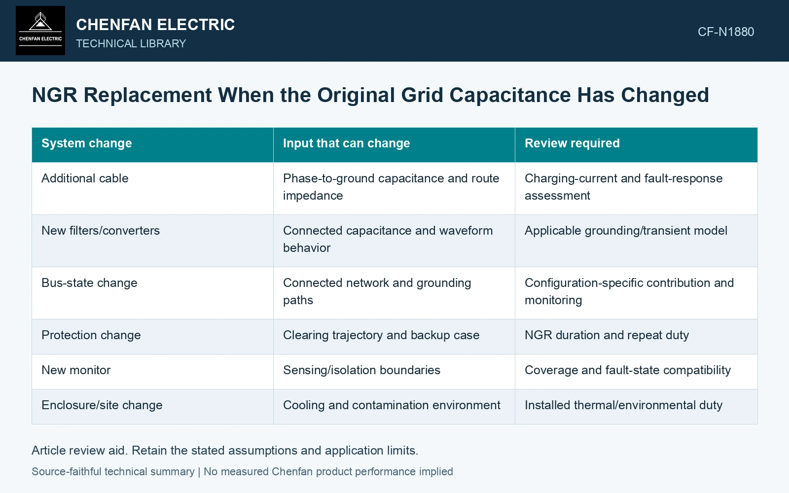
Record changes by their electrical consequence
| System change | Input that can change | Review required |
|---|---|---|
| Additional cable | Phase-to-ground capacitance and route impedance | Charging-current and fault-response assessment |
| New filters/converters | Connected capacitance and waveform behavior | Applicable grounding/transient model |
| Bus-state change | Connected network and grounding paths | Configuration-specific contribution and monitoring |
| Protection change | Clearing trajectory and backup case | NGR duration and repeat duty |
| New monitor | Sensing/isolation boundaries | Coverage and fault-state compatibility |
| Enclosure/site change | Cooling and contamination environment | Installed thermal/environmental duty |
Keep installed and connected populations distinct. A spare feeder can still contribute if its electrical boundary remains connected. A switched filter may govern one operating state even if it is absent most of the day.
Recheck the grounding objective
The resistor’s current contribution and the system’s charging current are different parts of the fault response. Increased capacitance can change the intended margin without changing the resistor’s cold ohms. Review the actual network under the accepted criteria instead of increasing or decreasing resistance by intuition.
Frequency-dependent and transient behavior may require more than a power-frequency capacitance sum. The new equipment’s circuit data and operating states determine whether the original model remains adequate. A converter label does not specify its effective phase-to-ground network.
Carry the updated event into every component
If fault clearing or source contribution changed, compare the new current and duration with elements, supports, neutral cable and associated devices. The previous equipment’s survival record applies to the duties it actually experienced, not automatically to the revised one.
A new monitor also needs the current assembly’s circuit identities. Its healthy indication cannot be interpreted using another model’s coverage assumptions.
Cable capacitance provides a parallel ground-fault current path and can affect grounding-resistor selection and ground-relay selectivity; historical mine-specific settings cannot be transferred to this circuit. [2]
Recalculate the connected capacitance budget
Assume balanced per-phase capacitance increases from 0.4 μF to 0.7 μF on a 6.6 kV line-to-line, 50 Hz system. Under full neutral displacement, 3ωCVph rises from 1.44 A to 2.51 A. Compare both with the independently specified resistor contribution and grounding objective; matching the old cold resistance does not preserve the previous charging-current relationship.
References
- IEEE, IEEE C57.32-2015, IEEE Standard for Requirements, Terminology, and Test Procedures for Neutral Grounding Devices (historical edition).
- T. Novak, J. Basar, J. Sottile and J. L. Kohler, The Effects of Cable Capacitance on Longwall Power Systems, IEEE Transactions on Industry Applications 40(5), 2004; DOI: 10.1109/TIA.2004.834025.