

Opening the supply breaker does not instantly make a motor bus electrically dead. Rotating machines and their remaining magnetic states can sustain a decaying voltage. The amplitude and phase evolve while the machines slow and connected loads change. [1]
The transformer has lost its supply role, but the bus still has dynamic sources and loads. This behavior is distinct from residual flux in an unloaded transformer core.
Keep magnetic and mechanical states separate
An induction motor’s flux and rotor current decay after disconnection, while its rotor slows according to inertia and load torque. These processes interact but do not have identical time histories. A slowly rotating machine can have weak terminal voltage if its magnetic state has decayed.
A synchronous machine adds its excitation-system state. A drive-connected motor has another interface between the machine and the AC bus. The connected-machine population therefore matters as much as its total installed power.
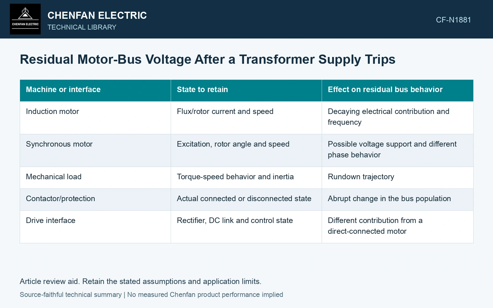
| Machine or interface | State to retain | Effect on residual bus behavior |
|---|---|---|
| Induction motor | Flux/rotor current and speed | Decaying electrical contribution and frequency |
| Synchronous motor | Excitation, rotor angle and speed | Possible voltage support and different phase behavior |
| Mechanical load | Torque-speed behavior and inertia | Rundown trajectory |
| Contactor/protection | Actual connected or disconnected state | Abrupt change in the bus population |
| Drive interface | Rectifier, DC link and control state | Different contribution from a direct-connected motor |
Solve the common bus, not independent voltages
All directly connected machines share one bus voltage. Their internal states and impedances determine currents into that network. Adding each machine’s assumed open-circuit voltage as if it were an isolated signal does not enforce that common boundary.
A dynamic model needs the connected network and consistent initial operating state. When a contactor drops out, the network changes. Its machine should not continue contributing simply because it remains in an aggregate motor nameplate list.
Expect a changing frequency trajectory
The SEL transfer paper emphasizes nonlinear voltage and frequency rundown. A constant frequency-difference assumption may approximate a short interval, but it should not be extended through the whole decay without checking the model or waveform.
Measured bus voltage should retain three-phase information and the source reference used for phase comparison. Near very low amplitude, phase and frequency estimates can become less reliable; the measurement method’s limits matter to transfer logic.
Positive- and negative-sequence machine states and the network need a coupled transient treatment when voltage becomes unbalanced. [2]
Distinguish a residual voltage from a speed reading
Assume a recorded motor remains at 0.9 pu mechanical speed while residual terminal voltage has fallen to 0.2 pu RMS. Neither value determines the other without magnetic and network states. Retain both channels and switching events when validating the transfer model; an inertia match alone cannot reconstruct the voltage trajectory.
References
- P. Muralimanohar, D. Haas, J. R. McClanahan, R. T. Jagaduri and S. Singletary, Implementation of a Microprocessor-Based Motor Bus Transfer Scheme, IEEE PCIC, 2016, DOI: 10.1109/PCICON.2016.7589248.
- W.-P. Liao, Y. Zhang and R. Zhou, Analytical method to calculate transient responses of induction motor load, IET Generation, Transmission & Distribution, 2020, DOI: 10.1049/iet-gtd.2018.6107.