

A grounding design can lose its intended margin as the network grows. Additional cable length, motors, filters and connected equipment add phase-to-ground capacitance. The transformer neutral resistor may be unchanged while the system it serves is no longer the one originally assessed. [1]
Build a capacitance budget for the relevant operating states. Include connected equipment, not simply installed equipment. A bus tie or switched filter can change the total during operation.
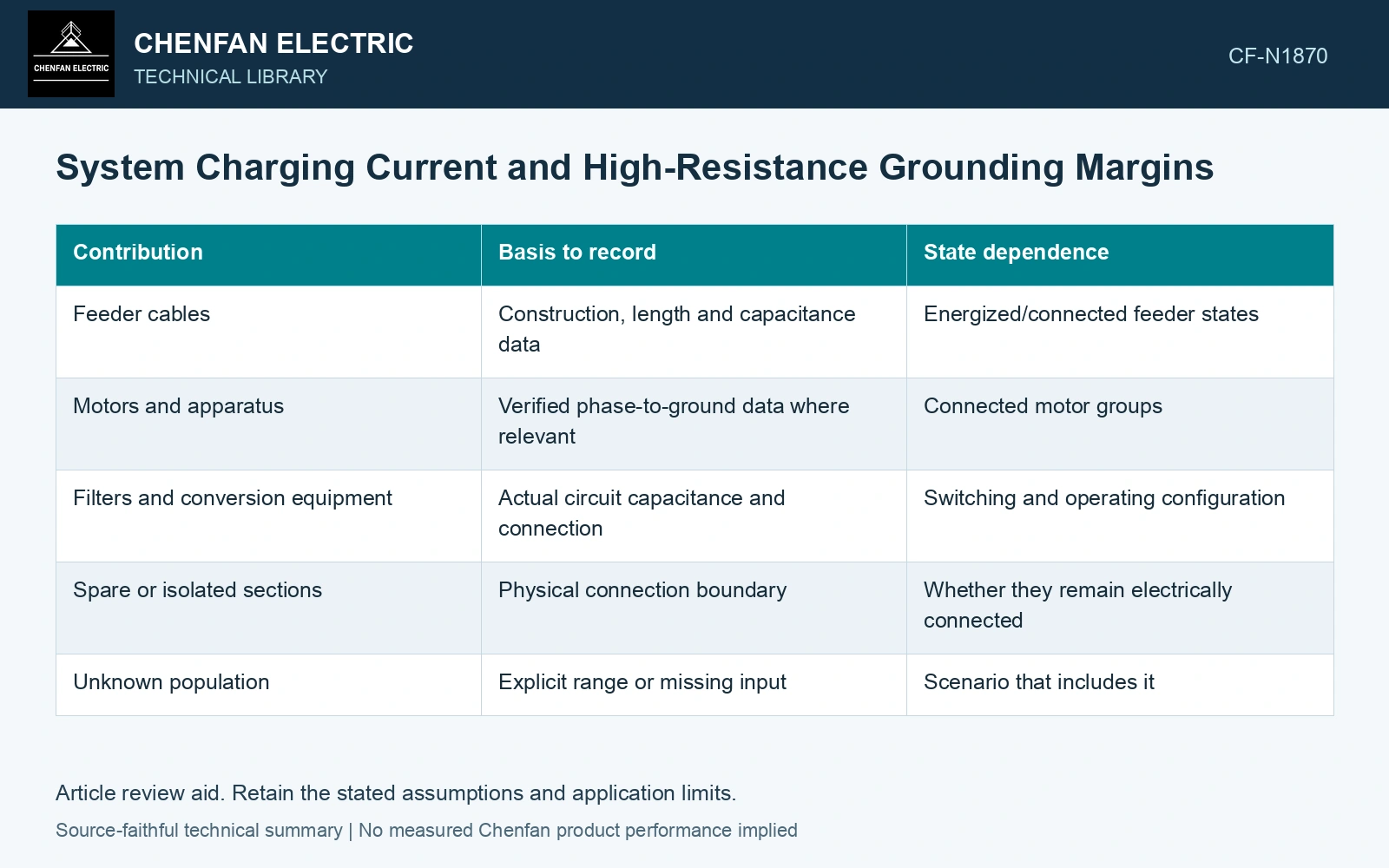
Keep capacitance entries traceable
| Contribution | Basis to record | State dependence |
|---|---|---|
| Feeder cables | Construction, length and capacitance data | Energized/connected feeder states |
| Motors and apparatus | Verified phase-to-ground data where relevant | Connected motor groups |
| Filters and conversion equipment | Actual circuit capacitance and connection | Switching and operating configuration |
| Spare or isolated sections | Physical connection boundary | Whether they remain electrically connected |
| Unknown population | Explicit range or missing input | Scenario that includes it |
Do not replace a missing value with zero because it is difficult to obtain. Preserve a justified range and show how the uncertainty affects the grounding conclusion.
Define the simplified charging-current estimate
For a balanced three-phase system with equal per-phase ground capacitance Cph, a common illustrative prospective charging-current magnitude under full neutral displacement is Ic ≈ 3ωCphVph. Ic is in amperes, ω = 2πf in radians per second, Cph is in farads and Vph is the normal phase-to-neutral voltage in volts.
The expression assumes sinusoidal frequency f, an idealized balanced capacitance network and the stated displacement condition. It is a starting estimate, not the actual earth-fault current of every resistor-grounded network. The grounding resistor, fault impedance, source and uneven capacitances affect the real response.
Compare the right current quantities
Separate the resistive grounding contribution from the capacitive system contribution and the total fault response. They are not scalar quantities that can always be added as magnitudes. Their phase relationships matter to the network calculation.
Cable capacitance forms a parallel ground-current path that changes feeder-relay visibility. [2] Keep that network current distinct from the resistor contribution when assessing the high-resistance grounding margin.
Compare capacitive and resistive components
Assume a balanced 6.6 kV, 50 Hz network has 0.6 μF phase-to-earth capacitance per phase. The simplified charging-current magnitude is 2.155 A. Against an assumed 5 A resistor contribution, the ratio is 2.32. The ratio documents this model only; the required margin and total fault current require the approved grounding assessment.
References
- IEEE, IEEE C57.32-2015, IEEE Standard for Requirements, Terminology, and Test Procedures for Neutral Grounding Devices (historical edition).
- T. Novak, J. Basar, J. Sottile and J. L. Kohler, The Effects of Cable Capacitance on Longwall Power Systems, IEEE Transactions on Industry Applications 40(5), 2004; DOI: 10.1109/TIA.2004.834025.