

A ceramic support’s temperature rating describes only part of its duty. In an NGR, one face can receive radiation from a hot element while another remains attached to a cooler frame. The resulting temperature gradient and restraint can matter more than the average temperature. [1]
The review should describe how heat enters the support and how it is allowed to deform. A high-temperature material label cannot establish resistance to every thermal shock, mounting load or contamination condition.
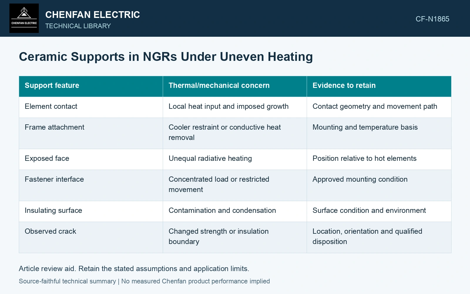
Locate the heat-entry surfaces
Identify direct metal contacts, exposed faces and airflow around each support. A small conductive contact can create a local hot region; radiation can heat one side preferentially. Nearby geometry determines exposure, so an identical support installed elsewhere may see another duty.
| Support feature | Thermal/mechanical concern | Evidence to retain |
|---|---|---|
| Element contact | Local heat input and imposed growth | Contact geometry and movement path |
| Frame attachment | Cooler restraint or conductive heat removal | Mounting and temperature basis |
| Exposed face | Unequal radiative heating | Position relative to hot elements |
| Fastener interface | Concentrated load or restricted movement | Approved mounting condition |
| Insulating surface | Contamination and condensation | Surface condition and environment |
| Observed crack | Changed strength or insulation boundary | Location, orientation and qualified disposition |
Separate gradient stress from imposed movement
A temperature gradient can make regions of the ceramic seek different expansion. External restraint can add another stress. In a simplified fully restrained uniform member, thermal stress depends on stiffness, expansion coefficient and temperature change, but a real brittle support’s geometry and temperature field require a more suitable assessment. A universal stress estimate from its maximum temperature would be misleading.
Element expansion also matters. A support may be exposed to moderate temperature yet receive a large force because the element’s movement is blocked. Inspect that load path rather than attributing every crack to excessive ceramic temperature.
Keep dielectric evidence distinct
Contamination across an insulating surface creates a different concern from a mechanical crack. Both can coexist. A favorable visual surface inspection cannot establish internal mechanical strength, and an intact body does not prove the surface remains suitable under the actual environment.
Thermal stress requires strain compatibility as well as a temperature field. Free expansion and restraint explain why a cooler region can enter tension while a hotter region enters compression. [2]
Resolve tension across an unevenly heated support
Assumptions: two equal-area axial strips represent adjacent regions of a ceramic support. Rigid end plates impose a common axial strain and prevent bending; the combined member is otherwise free of axial load. Both strips have E = 100 GPa and α = 6×10⁻⁶ K⁻¹. One strip rises 80 K and the other remains at its initial temperature. Force balance gives the common strain ε = α(80 + 0)/2 = 240 µε. From σ = E(ε − αΔT), the hot strip carries −24 MPa compression and the cool strip +24 MPa tension. If the project tensile acceptance gate is assumed to be 20 MPa at the cool-strip temperature, the cool region fails by 4 MPa, or 20%. Redesign the gradient or restraint before approval. The often-used EαΔT = 48 MPa instead describes a uniformly heated, fully fixed member; it is a different boundary condition. The actual support needs its geometry, bending freedom and qualified brittle-material strength. [2]
References
- IEEE, IEEE C57.32-2015, IEEE Standard for Requirements, Terminology, and Test Procedures for Neutral Grounding Devices (historical edition).
- U.S. Department of Energy, DOE-HDBK-1017/2-93, Material Science, Volume 2, 1993, Thermal Stress.