

A resistor element can heat much faster than the frame holding it. Its expansion is therefore a relative movement problem, even if both parts are made from metal. The assembly needs a deliberate path for that movement without overloading supports or destabilizing electrical connections. [1]
Begin with the actual element geometry and restraint arrangement. Long folded or grid elements can distribute movement through bends and supports; their behavior cannot always be represented by the overall enclosure length.
Trace the displacement to its restraint
For a straight, freely expanding, uniformly heated member, ΔL = αLΔT. ΔL and L use the same length unit, α is linear expansion coefficient in inverse kelvins and ΔT is temperature change in kelvins. For two members, compare their separate expansions along the relevant load path.
The formula is illustrative. A real element may have a nonuniform temperature, shaped geometry and partial restraint. Its actual movement and stress need an applicable model or qualified construction evidence.
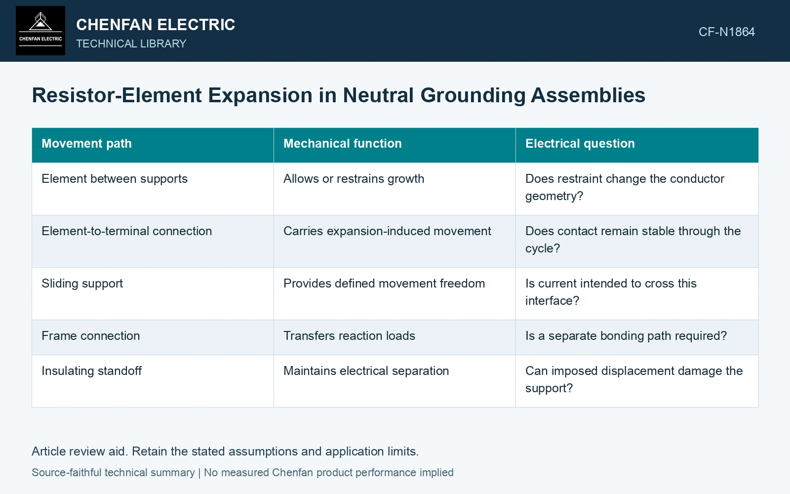
| Movement path | Mechanical function | Electrical question |
|---|---|---|
| Element between supports | Allows or restrains growth | Does restraint change the conductor geometry? |
| Element-to-terminal connection | Carries expansion-induced movement | Does contact remain stable through the cycle? |
| Sliding support | Provides defined movement freedom | Is current intended to cross this interface? |
| Frame connection | Transfers reaction loads | Is a separate bonding path required? |
| Insulating standoff | Maintains electrical separation | Can imposed displacement damage the support? |
Do not confuse slip with electrical continuity
A support can be designed to slide mechanically without serving as a conductive joint. Conversely, a connection that carries current may need stable pressure and a controlled contact surface. Treating an arbitrary sliding contact as both functions leaves wear and contact resistance unresolved.
Check the direction in which movement is permitted. A slot that accommodates horizontal growth may still restrain a vertical or rotational component. Neighboring elements and clearances must remain compatible throughout the accepted movement range.
Include cooling in the cycle
When the element cools, movement reverses. Friction, retained deformation or a shifted support can make the return path differ from the heating path. Repeated movement can load joints and supports differently from a single fault test.
Inspect the relevant interfaces using identified locations: cracked supports, displaced washers, element distortion and changed joint condition. These observations do not individually quantify fatigue life, but they can reveal that the intended movement path is no longer working as designed.
Calculate free growth for each load-carrying member before imposing compatibility. Restricting differential expansion introduces thermal stress; allowing motion requires usable travel in the actual direction of growth. [2]
Compare element and frame growth
Assumptions: the straight effective element length is 1.5 m, α is 16×10⁻⁶ K⁻¹ and its uniform rise is 300 K. Free element growth is 7.2 mm. A same-length frame with assumed α = 12×10⁻⁶ K⁻¹ and rise 50 K grows 0.9 mm, leaving 6.3 mm relative travel. If the installed sliding path has only 5.0 mm usable one-way travel, it is short by 1.3 mm. With an assumed installation margin of 1.0 mm, require at least 7.3 mm usable one-way movement from the cold installed position. Reject the 5.0 mm arrangement and revise the movement path; nominal slot length alone does not prove this travel. Verify contact stability separately from mechanical sliding. [2]
References
- IEEE, IEEE C57.32-2015, IEEE Standard for Requirements, Terminology, and Test Procedures for Neutral Grounding Devices (historical edition).
- U.S. Department of Energy, DOE-HDBK-1017/2-93, Material Science, Volume 2, 1993, Thermal Stress.