

A pipe connected to a tank nozzle can apply forces and moments from weight, pressure, thermal movement and installation mismatch. The tank shell responds locally. A weld check that assumes an immovable nozzle can miss both shell deformation and piping-load redistribution. [1]
Define a coordinate system at the nozzle and record Fx, Fy, Fz, Mx, My and Mz. Forces are newtons and moments N·m. Keep the application point and signs consistent between piping and tank models.
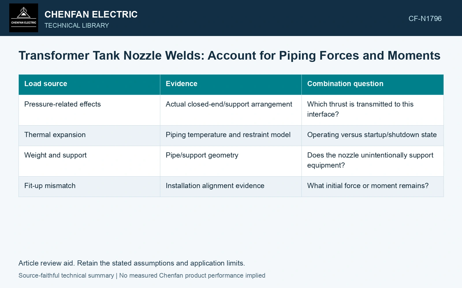
| Load source | Evidence | Combination question |
|---|---|---|
| Pressure-related effects | Actual closed-end/support arrangement | Which thrust is transmitted to this interface? |
| Thermal expansion | Piping temperature and restraint model | Operating versus startup/shutdown state |
| Weight and support | Pipe/support geometry | Does the nozzle unintentionally support equipment? |
| Fit-up mismatch | Installation alignment evidence | What initial force or moment remains? |
Use compatible flexibility
The pipe model and shell model should share the nozzle flexibility or a justified boundary approximation. A very stiff piping assumption can overstate one load while understating movement elsewhere. Compare sensitivity where the interface data are uncertain.
For a simple closed-end pressure screen, F = pA gives newtons from pascals and m². Whether that force reaches the nozzle depends on the actual restraint and pressure boundary; it must not be added indiscriminately to every pipe load.
Choose NDT using material, weld thickness, welding process, quality requirements and demonstrated coverage. NDT acceptance levels are not a detailed one-to-one translation of weld quality levels. [2]
Carry the pipe moment to the nozzle
Assumptions for a preliminary nominal-section screen: the pipe applies 2 kN transverse force at a 0.4 m lever arm, giving 0.8 kN·m (800,000 N·mm). The assessed section modulus is 8,000 mm³, other tensile membrane stress at the same section is 20 MPa, and its project nominal-stress gate is 110 MPa. Bending adds M/Z = 100 MPa, giving 120 MPa and a 10 MPa failure. The available bending moment is (110 − 20)×8000 = 720,000 N·mm, corresponding to only 1.8 kN at that lever arm. Reject the 2 kN case and revise support/load transfer. Local shell stress, flexibility and weld details require the approved model; this nominal calculation cannot qualify the nozzle alone.
References
- U.S. Federal Highway Administration, Bridge Welding Reference Manual, FHWA-HIF-19-088, 2019.
- ISO, ISO 17635:2025, Non-destructive testing of welds — General rules for metallic materials.