

A large tank opening interrupts the shell’s stiffness. Welding around its perimeter changes restraint as segments join and the loop closes. The final shape depends on that evolving structure, not only on the amount of deposited weld. [1]
Record the opening geometry, nearby stiffeners, temporary fixtures and planned weld segments. Identify when the opening is cut and when the ring, nozzle or attachment is fitted. These stages can have different stiffness and freedom to move.
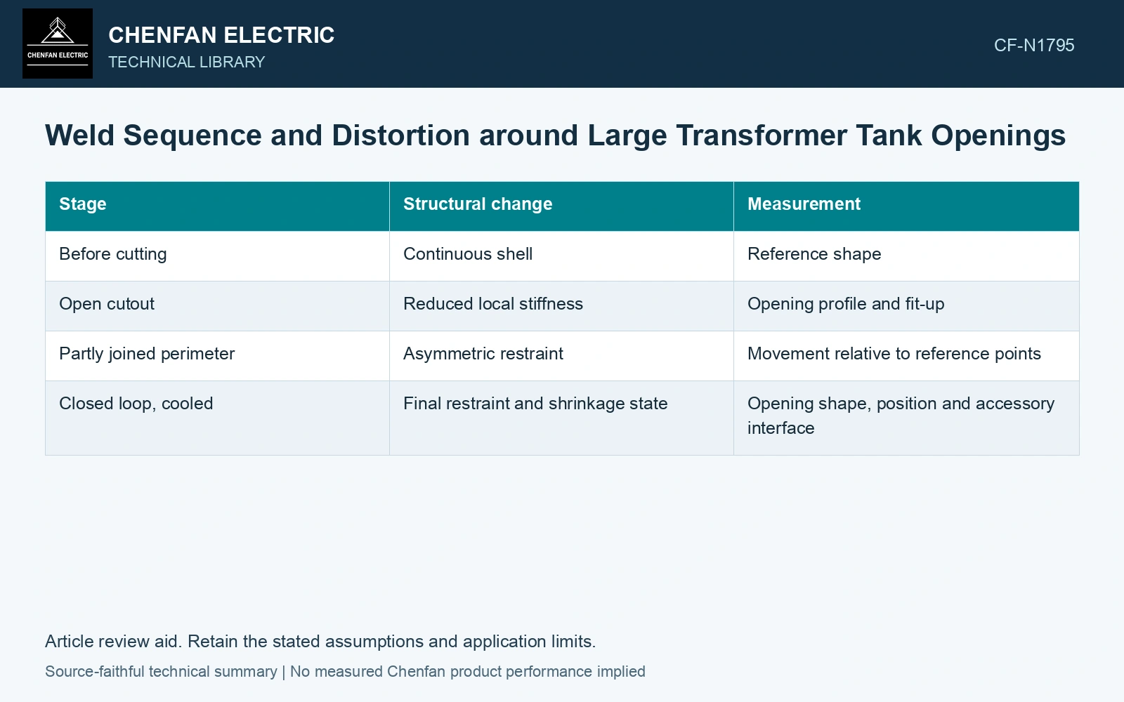
Map the evolving constraints
| Stage | Structural change | Measurement |
|---|---|---|
| Before cutting | Continuous shell | Reference shape |
| Open cutout | Reduced local stiffness | Opening profile and fit-up |
| Partly joined perimeter | Asymmetric restraint | Movement relative to reference points |
| Closed loop, cooled | Final restraint and shrinkage state | Opening shape, position and accessory interface |
Compare sequences by the final function
Use representative fabrication evidence or a qualified thermal/mechanical model for alternative sequences. Keep fixtures, heat-input basis and measurement state consistent. A sequence that reduces one diameter change can still shift the opening centre or distort a sealing face.
Define the dimensions needed by the accessory: shape, axis or plane, bolt pattern and sealing geometry. A least-squares fitted circle can hide a local departure; use the functional tolerances specified by the drawing.
Choose NDT using material, weld thickness, welding process, quality requirements and demonstrated coverage. NDT acceptance levels are not a detailed one-to-one translation of weld quality levels. [2]
Compare restrained and released opening shape
Assumptions: a nominal 1,000 mm opening has 1,000/998 mm axes while fixtured and 1,003/996 mm after cooling and fixture release. Diameter spread grows from 2 to 7 mm. If the drawing’s final released-state ovality allowance is assumed to be 4 mm, the first reading appears to pass but the final opening fails by 3 mm. An assumed alternative weld/fixture sequence giving released axes of 1,001/998 mm has 3 mm spread and passes this one geometric screen. Carry that sequence forward for qualification of centre position, sealing plane, bolt pattern and weld quality; the diameter result alone does not select a complete fabrication process.
References
- U.S. Federal Highway Administration, Bridge Welding Reference Manual, FHWA-HIF-19-088, 2019.
- ISO, ISO 17635:2025, Non-destructive testing of welds — General rules for metallic materials.