

A variable shunt reactor’s terminal MVAr rating does not define every tap-changer duty. The regulating connection and turns per step determine step voltage; a design with approximately constant MVAr increments can have its highest step voltage near the lowest MVAr position. [1] Calculate each section and switching duty from the winding diagram.
Obtain the actual winding diagram. Identify active turns, regulating sections, bypassed portions and the connections used at each tap. Section currents and tap duties must be derived from the actual regulating connection.
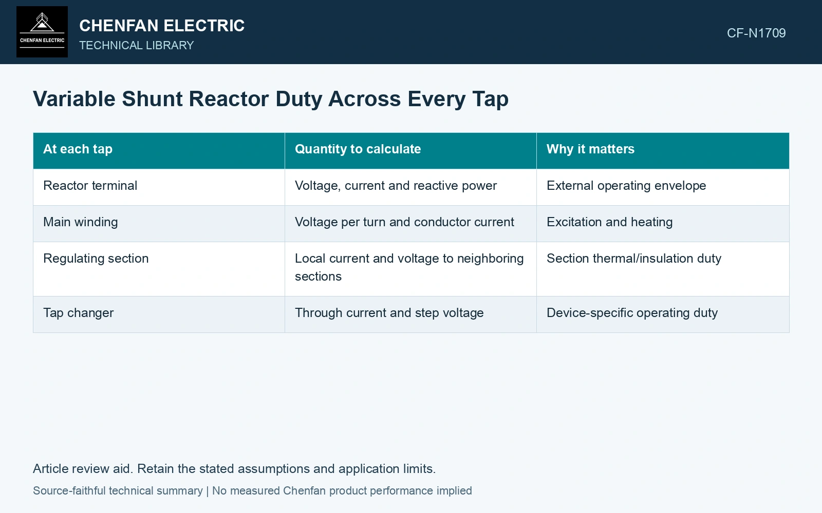
Build the section-duty map
| At each tap | Quantity to calculate | Why it matters |
|---|---|---|
| Reactor terminal | Voltage, current and reactive power | External operating envelope |
| Main winding | Voltage per turn and conductor current | Excitation and heating |
| Regulating section | Local current and voltage to neighboring sections | Section thermal/insulation duty |
| Tap changer | Through current and step voltage | Device-specific operating duty |
Use a simple relation only at the right boundary
For a balanced linear shunt reactor, Q = 3Vph²/(ωL) = VLL²/(ωL), with RMS volts, ω = 2πf in rad/s, L in henries and Q in vars. Under fixed linear magnetic reluctance, L scales with N², so Q scales with 1/N². This terminal relation does not give each internal section’s duty. [2]
At fixed voltage, increasing effective inductance lowers terminal reactive current. Internal regulating arrangements still need their own circuit calculation. If excitation is nonlinear or harmonic content matters, preserve the waveform rather than relying on a single L.
For simple series turn regulation, a ΔN-turn step has induced voltage VphΔN/N at the stated active-turn position. Other regulating circuits need their own connection model. [2]
Compare reactive duty across taps
Assumptions: a balanced 100 kV line-to-line, 50 Hz reactor uses simple series turn regulation and fixed linear reluctance. At 1,000 active turns it absorbs 30 Mvar. Taps at 1,095 and 1,225 turns give 25.02 and 19.99 Mvar, approximately equal 5 Mvar increments. The 95-turn step at the 1,000-turn position sees 5.485 kV RMS; the 130-turn step at 1,095 turns sees 6.854 kV RMS. Against an assumed 6 kV step-voltage ceiling, the lower-MVAr transition fails by 0.854 kV. Phase currents are 173.21, 144.45 and 115.42 A RMS; all pass an assumed 180 A through-current ceiling. Hold the tap duty despite the lower terminal current. [2]
References
- A. K. Nilakantan, K. Viereck and A. Krämer, Variable Active and Reactive Power Control Using OLTC in the Power Network, Maschinenfabrik Reinhausen, section 3.
- U.S. Department of Energy, DOE-HDBK-1011/4-92, Electrical Science, Volume 4, 1992.