

An LCC converter needs a suitable voltage-time opportunity for valve commutation and recovery. Transformer ratio affects the valve-side voltage, while network voltage, DC current, overlap and control determine the operating margin. The transformer is one part of this relationship. Apply the HVDC transformer specification framework of IEC/IEEE 60076-57-129 to the stated liquid-immersed equipment [1].
Define the converter operating point before discussing an extinction-angle margin. Record AC terminal voltage, transformer tap, DC current and the control mode. During a voltage depression, retain the waveform and phase shift rather than substituting only its RMS magnitude.
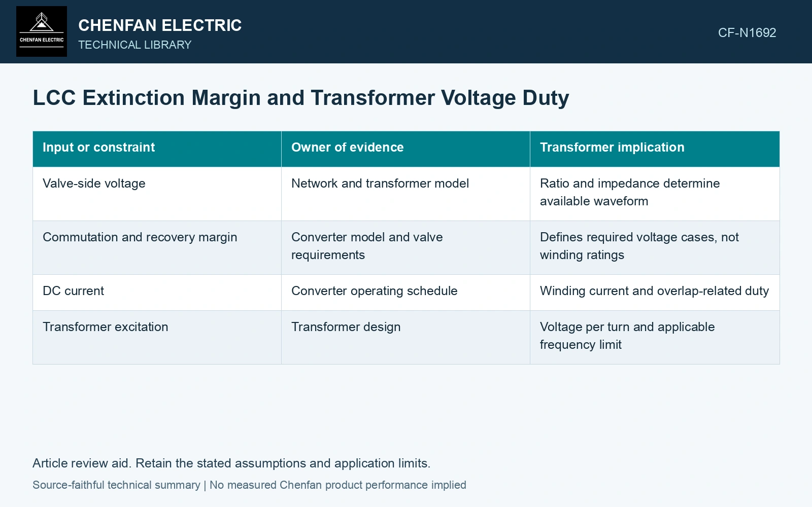
Connect the relevant inputs without merging their limits
| Input or constraint | Owner of evidence | Transformer implication |
|---|---|---|
| Valve-side voltage | Network and transformer model | Ratio and impedance determine available waveform |
| Commutation and recovery margin | Converter model and valve requirements | Defines required voltage cases, not winding ratings |
| DC current | Converter operating schedule | Winding current and overlap-related duty |
| Transformer excitation | Transformer design | Voltage per turn and applicable frequency limit |
A voltage increase is not a free margin increase
A different tap can increase the valve-side voltage for a given AC system condition. It also changes current, voltage per turn or other operating quantities according to the winding arrangement and control response. Check the complete operating point rather than assuming a ratio change solves one constraint without moving another.
Tap-changing response is much slower than the fast electrical events involved in a commutation disturbance. Use the actual controller and mechanism timing. A feasible steady tap cannot be treated as an instantaneous remedy for an AC voltage dip.
Check voltage benefit against excitation movement
Assume a 50 Hz steady operating point with valve-side voltage 100 kV RMS and unchanged grid-side applied voltage. A ratio change that raises valve-side voltage to 105 kV increases the valve-side no-overlap voltage scale by 5%. It does not establish a 5% increase in extinction angle. If the selected arrangement also raises voltage per active turn by 5%, normalized excitation moves from 1.00 to 1.05. Carry both changes into the converter and transformer models; accept the tap only when both feasible envelopes overlap.
Build cases at the actual system boundary
Evaluate the required voltage envelope, high-current conditions and relevant AC disturbances. For each case, report converter margin, winding current and transformer voltage constraints separately. If the converter model changes control mode during recovery, retain that transition in the duty definition.
At each station point, compare the converter requirement and transformer insulation, current and thermal limits. A control target does not replace an equipment acceptance value. The binding requirement is the one that restricts their shared feasible point.
Include normal converter operation and converter-side faults in the transformer transient study [2].
References
- IEC/IEEE, IEC/IEEE 60076-57-129:2017, Power transformers – Part 57-129: Transformers for HVDC applications.
- CIGRE WG B4.51, Technical Brochure 609, Study of Converter Transients Imposed on the HVDC Converter Transformers, 2015.