

An LCC station’s tap range must support its required DC voltage across the AC system voltage envelope. The converter control angle, current and commutation drop also affect the result. Selecting taps from the nominal AC/DC ratio alone can leave no usable control range at an endpoint. Apply the HVDC transformer specification framework of IEC/IEEE 60076-57-129 to the stated liquid-immersed equipment [1].
For an ideal six-pulse controlled bridge under stated conventions, a simplified average relation is Vd ≈ Vd0cos α − ΔVcomm. Vd0 is the no-overlap average DC voltage associated with the actual valve-side AC voltage; α is firing delay; ΔVcomm is the commutation-related drop. All voltages must use consistent sign and bridge orientation.
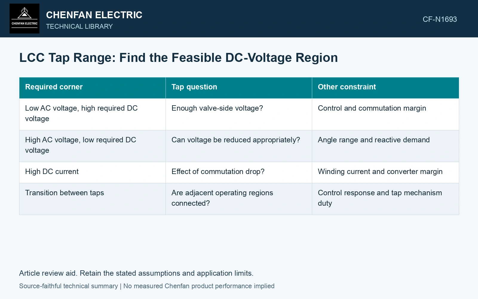
Use the relation to organize, not replace, the station model
| Required corner | Tap question | Other constraint |
|---|---|---|
| Low AC voltage, high required DC voltage | Enough valve-side voltage? | Control and commutation margin |
| High AC voltage, low required DC voltage | Can voltage be reduced appropriately? | Angle range and reactive demand |
| High DC current | Effect of commutation drop? | Winding current and converter margin |
| Transition between taps | Are adjacent operating regions connected? | Control response and tap mechanism duty |
The simplified bridge relation does not represent every inverter convention, disturbance or multi-bridge station. Use the actual topology and controls for final cases. Its value is to expose the inputs that a ratio-only calculation omits.
Reject a tap whose cosine solution is unreachable
Assume a rectifying continuous-current case with Vd0 = 600 kV, commutation drop 20 kV and required Vd = 550 kV. Then cos α = (550 + 20)/600 = 0.95 and α = 18.19°. At an assumed 10% AC-voltage depression, Vd0 falls to 540 kV; the same request needs cos α = 570/540 = 1.0556 and has no real solution. Even at α = 0°, output is only 520 kV, leaving a 30 kV shortfall. Mark that corner infeasible before checking current and reactive limits.
Mark the feasible cells
For each actual tap, solve the required AC/DC corners. Record control angle, winding current, reactive demand and transformer voltage constraints. Mark a cell feasible only when all conditions are met. If the control can reach Vd but reactive duty or current is excessive, the cell still fails.
Then check how the operating point moves between adjacent taps. Dead regions or excessive switching duty can matter even when isolated endpoints look acceptable. Do not assume a slow tap changer follows fast DC-voltage requests.
Test the tap endpoints at the required operating corners and control states. Any unsatisfied corner limits the usable range even when the percentage span looks generous. Select the range from those cases and retain the control assumption responsible for each exclusion.
Include normal converter operation and converter-side faults in the transformer transient study [2].
References
- IEC/IEEE, IEC/IEEE 60076-57-129:2017, Power transformers – Part 57-129: Transformers for HVDC applications.
- CIGRE WG B4.51, Technical Brochure 609, Study of Converter Transients Imposed on the HVDC Converter Transformers, 2015.