

A GSU tap that works at rated megawatts and nominal grid voltage may fail at a reactive-power endpoint. Tap selection should cover the operating envelope the plant must deliver, including seasonal grid voltage and the generator’s permitted terminal-voltage range. Keep the selected winding arrangement within the general power-transformer specification framework [1].
Define a as the selected HV/LV line-voltage ratio. In a no-load first pass, VLV ≈ VHV/a. If both grid extremes must remain inside the same LV voltage band at one fixed tap, the no-load intersection is VHV,max/VLV,max ≤ a ≤ VHV,min/VLV,min. This interval can be empty. Where the dispatch specification pairs different voltage bands with different grid states, derive the intersection from those required pairs instead.
Bring reactive duty into the screening
Under load, leakage impedance produces a phasor voltage difference. Its effect depends on both P and Q and the adopted sign convention. A scalar “percentage regulation” copied from one power-factor test should not be added to every case with the same sign.
Calculate the terminal voltage for each candidate tap using the plant load-flow model. Retain the excitation and stator-current limits at the calculated voltage. If an operating point requires a generator voltage outside its permissible range, increasing excitation is not a complete remedy.
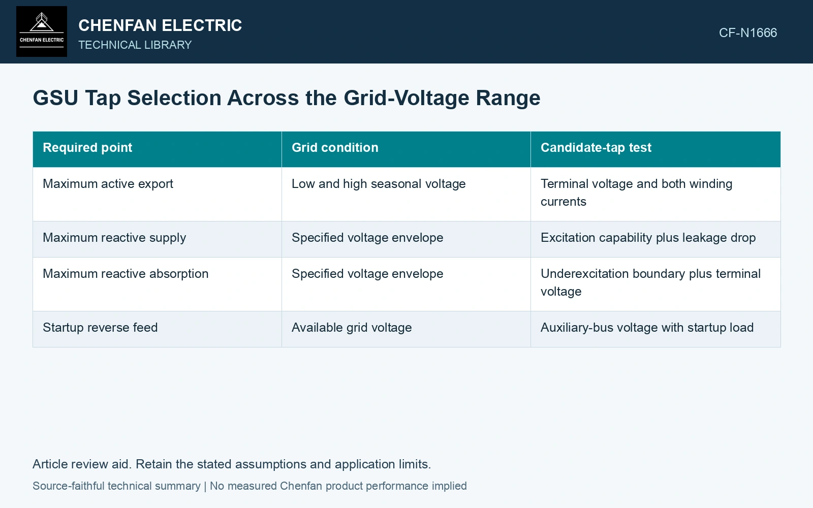
| Required point | Grid condition | Candidate-tap test |
|---|---|---|
| Maximum active export | Low and high seasonal voltage | Terminal voltage and both winding currents |
| Maximum reactive supply | Specified voltage envelope | Excitation capability plus leakage drop |
| Maximum reactive absorption | Specified voltage envelope | Underexcitation boundary plus terminal voltage |
| Startup reverse feed | Available grid voltage | Auxiliary-bus voltage with startup load |
Identify an empty no-load tap intersection
Assume required 50 Hz grid voltages from 380 to 420 kV and a generator no-load band from 19 to 21 kV. A fixed line-voltage ratio must satisfy 420/21 ≤ a ≤ 380/19, giving exactly a = 20.0. Tightening the assumed machine band to 19.5–20.5 kV instead requires 20.488 ≤ a ≤ 19.487, an empty interval. The first screen has no spare margin and the second has no fixed-tap solution. Resolve the required voltage pairs or ratio-control strategy before adding loaded P–Q constraints.
Mark why a tap fails
Use one row per required operating point and one column per actual tap. Enter the calculated voltage, current and binding limit. A blank or green cell without calculation loses the reason for the decision. Keep the physical tap identification consistent with the transformer ratio-test record.
If no tap covers the full envelope, determine whether the requirement needs an on-load ratio change, a revised voltage range or another system measure. De-energized taps cannot be treated as continuous operational controls. The tap specification should state when a change is allowed and which startup or dispatch states use each position.
The result is a feasible region with named exclusions. It provides a stronger design input than selecting the middle tap and expecting the generator regulator to absorb every remaining difference.
Verify the selected terminal ratio with a test method matched to the winding connection [2].
References
- IEC, IEC 60076-1:2011, Power transformers – Part 1: General.
- Ohlen, M., and Werelius, P., A Guide to Transformer Ratio Measurements, Megger Sweden, 2010-01-18, Definitions and TTR measurements.