

“Unit stopped” is too vague to describe a generator-transformer connection. With a transmission breaker closed, the GSU may remain energized while the generator breaker is open. With no generator breaker, the electrical boundary may be much farther from the machine. Use IEC 60076-1 for general transformer specification [1].
Divide the single-line diagram into sections separated by actual interrupting or isolating devices. Label the generator terminals, the conductor between generator breaker and GSU, the GSU HV terminals and each auxiliary tee. Then assign possible sources to each section. Include emergency and test supplies where they exist.
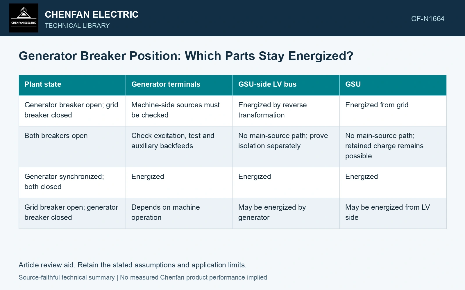
An example matrix for a unit with a generator breaker
| Plant state | Generator terminals | GSU-side LV bus | GSU |
|---|---|---|---|
| Generator breaker open; grid breaker closed | Machine-side sources must be checked | Energized by reverse transformation | Energized from grid |
| Both breakers open | Check excitation, test and auxiliary backfeeds | No main-source path; prove isolation separately | No main-source path; retained charge remains possible |
| Generator synchronized; both closed | Energized | Energized | Energized |
| Grid breaker open; generator breaker closed | Depends on machine operation | May be energized by generator | May be energized from LV side |
The matrix deliberately distinguishes “no main-source path” from a verified safe working condition. Use it to map possible energy paths. Isolation, testing for absence of voltage and earthing remain governed by the approved plant procedure.
Put the auxiliary tee on the correct side
A tee between the generator breaker and GSU can remain available with the machine disconnected. A tee on the generator side may lose supply or require another path. Draw the tee explicitly rather than attaching it to a generic line labelled “generator bus.”
Instrument transformers and arresters inherit the state of the conductor they touch. Their secondary indications can mislead if a drawing revision moved the primary connection but the operating description did not change. List the measuring point beside each voltage indication used by operators.
Mark the voltage up to the open breaker
Assume a 400 kV grid and GSU ratio 20, with grid breaker closed and generator breaker open. The connected GSU-side LV bus is approximately 20 kV. The machine-side zero indication does not remove this source. Mark both sections before defining the work boundary.
Use the matrix to check a maintenance boundary
Choose the equipment to be worked on and list every state that can energize it. Examine paths through the GSU, auxiliary transformer, interconnecting bus and temporary test connections. Check whether a breaker is an adequate isolating device for that specific work under the plant rules.
A good state matrix answers a narrow question accurately: which sections can receive energy in this configuration? It should never imply that a stop command, an open breaker indication or a zero meter reading alone establishes isolation.
Apply the plant isolation procedure to every identified energy source [2].
References
- IEC, IEC 60076-1:2011, Power transformers – Part 1: General.
- U.S. Occupational Safety and Health Administration, 29 CFR 1910.147, The control of hazardous energy (lockout/tagout), official text accessed 2026-10-24.