

A dispatch model uses terminal powers, while the transformer has internal conductor, magnetic, insulation and cooling limits. A capability map connects those two descriptions. It should not consist only of independent MVA boxes at the three terminals.
For each tap and connection, derive the internal-current map iw = Ait + iexc, where it contains consistently referenced terminal current phasors and iw the relevant winding currents. Matrix A comes from the actual connectivity and ampere-turn relationships; iexc represents excitation where the model retains it. The excitation term depends on voltage and magnetic state; use a frequency-domain model appropriate to the study.
Transform the constraints
Apply verified limits to each mapped winding current, such as |iw,k| ≤ Ik,limit under the stated temperature and cooling condition. Add the corresponding voltage, flux, auxiliary and thermal constraints. Convert terminal currents to complex powers using the actual voltage and phase connection. Keep connection, tapping and network assumptions explicit in the application assessment [1].
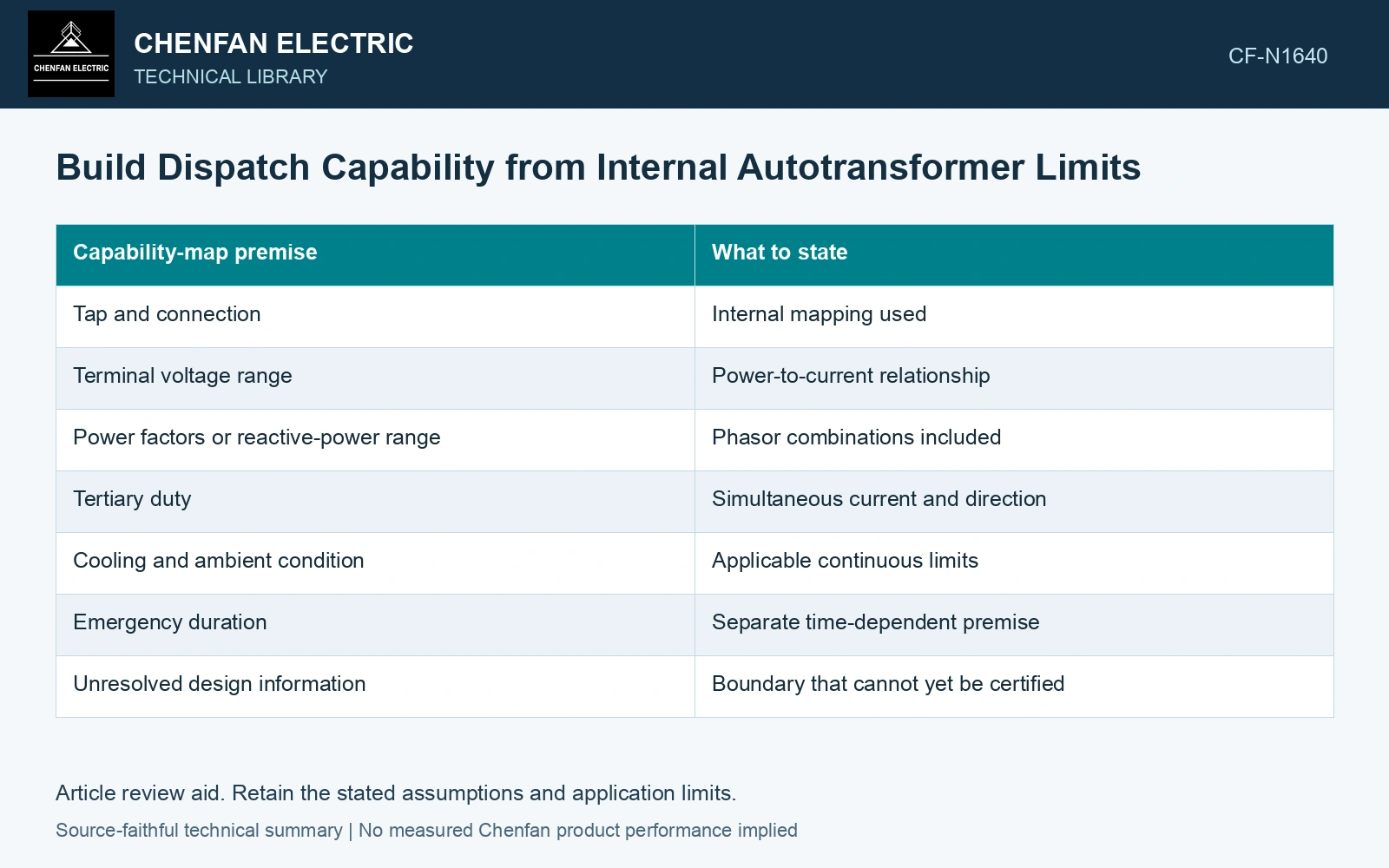
| Capability-map premise | What to state |
|---|---|
| Tap and connection | Internal mapping used |
| Terminal voltage range | Power-to-current relationship |
| Power factors or reactive-power range | Phasor combinations included |
| Tertiary duty | Simultaneous current and direction |
| Cooling and ambient condition | Applicable continuous limits |
| Emergency duration | Separate time-dependent premise |
| Unresolved design information | Boundary that cannot yet be certified |
For a fixed tertiary condition and voltage, a two-dimensional main-port map is a slice of the complete feasible set. Another tertiary load or reactive-power state can produce a different boundary. Label the slice rather than presenting it as universal.
Identify the active limit
At each boundary segment, record which winding or other duty is limiting. A common-section current constraint may govern one power-flow direction while the series section governs another. This information makes the map useful for reviewing a requested dispatch change.
Check corner and combined-load states. Independent terminal caps can miss a simultaneous combination that overloads an internal section, even though every port remains below its own cap.
Keep tap transitions and regulating restrictions separate where the physical operation imposes them. A feasible steady-state point is not automatically reachable through every switching sequence.
Verify the map’s basis
Use manufacturer-approved or otherwise verified internal limits and their reference conditions. A nameplate terminal rating alone may not supply all information needed for a multiport capability region.
Test the mapping with known operating states and current closure. Compare measured or validated internal-current evidence where available. Do not tune the map merely to reproduce the largest historical dispatch point; operating history is not a complete qualification boundary. Assess the relevant measured quantities with a defined measurement model and propagated uncertainty [2].
The resulting capability description names the limiting mechanism and the conditions under which the point is acceptable. That gives dispatch studies a physical constraint rather than a convenient terminal-power limit that quietly ignores the winding section carrying the actual current.
Locate the common-section boundary at one dispatch slice
Assumptions for a sinusoidal, single-phase slice at 50 Hz: H/L/T voltages are 100/80/10 kV RMS, turn ratios are 100:80:10, low-port current is 100 A leaving L, and tertiary current is 100 A entering its dotted end. Neglect excitation and losses. Ampere-turn balance gives IH = (80×100 − 10×100)/100 = 70 A; IC = 70 − 100 = −30 A. Inputs of 7 MVA at H and 1 MVA at T balance 8 MVA delivered at L. With an assumed continuous common-section limit of 25 A at the specified cooling state, utilization is 30/25 = 120%. Reject this slice point even if all terminal MVA limits pass; reduce the combined loading until the common current is within its verified limit. Record rated quantities and test conditions on the general power-transformer basis of IEC 60076-1 [3].
References
- IEC, IEC 60076-8:1997, Power transformers – Part 8: Application guide, 1997, official public scope.
- JCGM, JCGM 100:2008, Evaluation of measurement data — Guide to the expression of uncertainty in measurement, 2008.
- IEC, IEC 60076-1:2011, Power transformers – Part 1: General.