

A single-phase autotransformer bank contains separate magnetic units, but its neutrals can be connected through a shared conductor and grounding system. That electrical topology governs part of its unbalanced response. Separate cores do not make the connected phases electrically independent.
Map the neutral terminal of each unit, the bonds between them and every connection to the external return network. Include the impedances that matter at the frequency and event being studied. An ideal common node is an assumption, not a photograph of a long installed conductor.
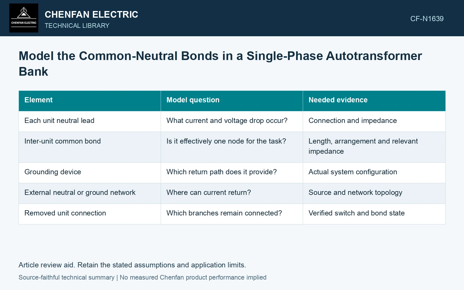
Preserve the bond geometry as circuit branches
| Element | Model question | Needed evidence |
|---|---|---|
| Each unit neutral lead | What current and voltage drop occur? | Connection and impedance |
| Inter-unit common bond | Is it effectively one node for the task? | Length, arrangement and relevant impedance |
| Grounding device | Which return path does it provide? | Actual system configuration |
| External neutral or ground network | Where can current return? | Source and network topology |
| Removed unit connection | Which branches remain connected? | Verified switch and bond state |
For phase currents referenced consistently, neutral current is their signed sum. In symmetrical components, that sum is 3I0. This identity does not determine how the current divides among several neutral bonds and grounding branches; solve their network.
Rebuild the state when one unit is unavailable
Removing a unit from service can change the connected conductors, source paths and grounding relationship. Do not merely set that phase’s load to zero while retaining every original connection unless that matches the physical state.
Identify whether a neutral bond remains connected and whether any winding or terminal can be energized through the remaining network. The assessment must follow the actual isolation boundary.
Compare the resulting sequence and phase-domain behavior as appropriate. A balanced per-phase model may be inadequate for an asymmetric bank state. Use the actual winding and tertiary arrangement for each unit.
Distinguish local neutral voltage from system reference
Finite bond impedance can create potential differences between nominally common points. Their relevance depends on neutral current and the physical interface being assessed. Keep local ground rise separate from conductor voltage drop where both matter.
Check current closure at each neutral node and across the complete network. A missing bond can produce incorrect apparent independence; an extra ideal bond can suppress a real potential difference. Keep connection, tapping and network assumptions explicit in the application assessment [1].
Compare the electrical boundaries that change with unit availability and those that remain shared through the installed neutral bonds. Retain the actual bond impedances wherever unequal neutral potential affects the bank assessment.
Calculate the voltage across a finite common bond
Assume a 50 Hz neutral-node injection of 100 A RMS and two purely resistive return branches of 0.10 Ω and 0.20 Ω to the same reference. The equivalent impedance is (1/0.10 + 1/0.20)−1 = 0.0667 Ω. Node rise is 6.67 V RMS, with 66.67 A and 33.33 A in the branches. Removing the second branch raises the node voltage to 10.0 V at the same injected current: a 50% increase. Replace these branch assumptions with the installed conductor and grounding impedances before judging insulation interfaces; an ideal common node would hide the calculated bond voltage. Record rated quantities and test conditions on the general power-transformer basis of IEC 60076-1 [2]. Assess the relevant measured quantities with a defined measurement model and propagated uncertainty [3].
References
- IEC, IEC 60076-8:1997, Power transformers – Part 8: Application guide, 1997, official public scope.
- IEC, IEC 60076-1:2011, Power transformers – Part 1: General.
- JCGM, JCGM 100:2008, Evaluation of measurement data — Guide to the expression of uncertainty in measurement, 2008.