

An open terminal can mean an external load is disconnected, a source is disconnected, or a conductor inside the regulating arrangement is interrupted. Those are different circuit states. The core excitation follows the voltage still applied across connected turns.
Draw the remaining circuit with actual switch positions. Identify which winding span is energized and which terminals retain induced or conductive potential. Do not infer the state from a label such as “low side open.”
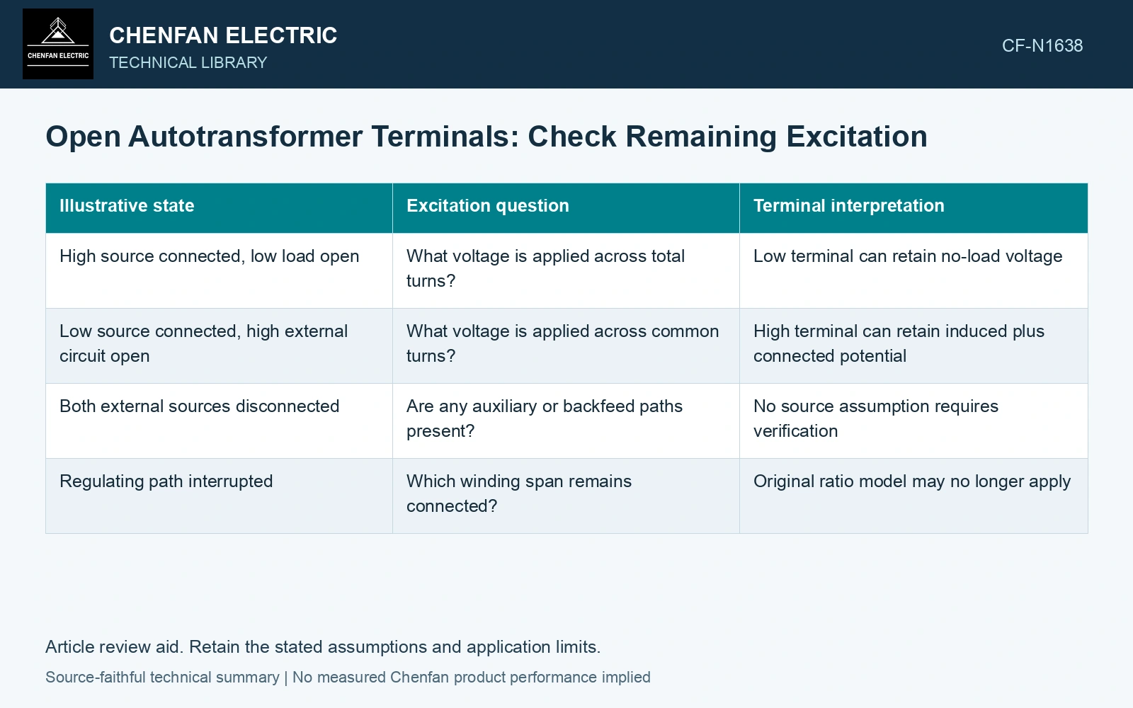
Compare defined states
| Illustrative state | Excitation question | Terminal interpretation |
|---|---|---|
| High source connected, low load open | What voltage is applied across total turns? | Low terminal can retain no-load voltage |
| Low source connected, high external circuit open | What voltage is applied across common turns? | High terminal can retain induced plus connected potential |
| Both external sources disconnected | Are any auxiliary or backfeed paths present? | No source assumption requires verification |
| Regulating path interrupted | Which winding span remains connected? | Original ratio model may no longer apply |
The table describes analytical states, not operating instructions. The actual unit may have additional connections that change each result.
Under an ideal common-flux model, induced voltage per turn is determined by the energized span. For a sinusoidal approximation, changing the applied voltage-to-turns ratio changes peak flux at fixed frequency and area. An open output alone does not force that ratio to zero.
Retain excitation current and magnetic history
With no external load, the source may still supply excitation current and losses. A simplified ideal load-current model that sets all currents to zero omits that behavior.
For an event study, include initial flux and the source switching waveform. The steady no-load relationship does not describe transient flux automatically. Residual magnetic state can matter even after external current paths change.
Grounding or bypass connections should be represented as actual circuit changes. They cannot be added to an unchanged ideal model merely as harmless labels. A bypass can create a different source or circulating path, while grounding a terminal can impose a new boundary condition. Keep connection, tapping and network assumptions explicit in the application assessment [1].
Identify every energized region
Report the remaining source, connected turns, volts-per-turn premise and expected terminal potentials. Include tertiary and regulating circuits where they can backfeed or alter excitation.
Use verified diagrams and qualified electrical procedures to establish the physical state. A voltage calculation is not permission to approach an open terminal or assume it is deenergized. Record rated quantities and test conditions on the general power-transformer basis of IEC 60076-1 [2].
The engineering conclusion should distinguish an unloaded winding from a winding without excitation. That distinction determines the magnetic assessment and prevents a system model from removing core flux merely because one external port has no output current.
Keep flux in the open-output calculation
Assume sinusoidal excitation at 50 Hz, 10 kV RMS across 1,000 connected turns, and effective steel area 0.030 m². Ignoring winding drops, Bpeak = V/(4.44fNA) = 1.502 T. Disconnecting only the external output load leaves that applied volts-per-turn and peak flux unchanged. If the same 10 kV is instead imposed across an assumed 900-turn span, the model gives 1.668 T, an 11.1% increase. The decision is therefore to retain the excitation branch and recalculate the energized span; zero output current is insufficient grounds for removing magnetic duty. Assess the relevant measured quantities with a defined measurement model and propagated uncertainty [3].
References
- IEC, IEC 60076-8:1997, Power transformers – Part 8: Application guide, 1997, official public scope.
- IEC, IEC 60076-1:2011, Power transformers – Part 1: General.
- JCGM, JCGM 100:2008, Evaluation of measurement data — Guide to the expression of uncertainty in measurement, 2008.