

An autotransformer’s common neutral participates in both connected voltage systems. Under unbalanced conditions, the current and potential depend on the available return paths and grounding impedances. A single isolated neutral resistor model can omit a significant system connection.
Draw the full zero-sequence network with explicit node references. Include the relevant source impedances, line paths, grounding devices, tertiary connection and common-neutral bond. Distinguish what is physically shared from what is merely labeled “ground.”
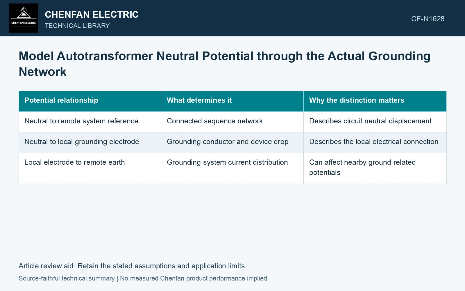
Keep three potentials separate
| Potential relationship | What determines it | Why the distinction matters |
|---|---|---|
| Neutral to remote system reference | Connected sequence network | Describes circuit neutral displacement |
| Neutral to local grounding electrode | Grounding conductor and device drop | Describes the local electrical connection |
| Local electrode to remote earth | Grounding-system current distribution | Can affect nearby ground-related potentials |
A neutral-to-reference voltage is not automatically the voltage across a nearby insulation interface. Its local grounded structure may also move in potential relative to remote earth. Use the reference appropriate to the physical question.
For symmetrical-component current defined as I0 = (Ia + Ib + Ic)/3, the neutral conductor current is the signed sum 3I0 under the relevant star connection. Keep signs from both sides of the autotransformer consistent; the common winding and terminal connection determine how those components combine.
Compare grounding paths as a network
Use Kirchhoff’s laws with the actual sequence impedances. Unequal grounding impedances change current division, but current does not divide according to grounding resistance alone when source and transformer impedances are material.
Evaluate the relevant system states, including unavailable sources or changed bonds. Record which grounds remain connected. A grounded-neutral assumption that was valid in the normal state may not describe a maintenance or fault configuration.
If a simplified admittance model is used, label every branch and its voltage reference. Solve the node voltage and branch currents together. A result that balances only current magnitudes can conceal incorrect phasor signs.
Use the result for the stated duty
Compare neutral and winding currents with their applicable limits, and provide the defined potential relationships to insulation or system studies. Do not convert the calculation directly into protection settings without the complete coordination assessment.
Check whether the transformer zero-sequence representation matches the actual winding and tertiary connections. A generic core model alone does not define conductive transfer between the two systems.
Label the current paths and voltage reference on the grounding-network result. Compare local insulation stress with the relevant local reference, and retain remote-earth voltage separately wherever the grounding circuit requires it.
Solve neutral displacement with two explicit returns
Assume a 50 Hz zero-sequence network injects 90 A RMS into a neutral with two resistive paths to the same remote reference, 0.30 Ω and 0.60 Ω. Nodal admittance is 5.0 S; neutral voltage is 90/5 = 18.0 V RMS, and branch currents are 60 A and 30 A. Using only the 0.30 Ω path would predict 27.0 V, 50% higher. If local metal is assumed to rise to 5.0 V relative to the remote reference, the neutral-to-local-metal duty is 13.0 V, rather than 18.0 V. Record both reference relationships before assigning a local insulation duty. Record rated quantities and test conditions on the general power-transformer basis of IEC 60076-1 [1]. Assess the relevant measured quantities with a defined measurement model and propagated uncertainty [2]. Keep connection, tapping and network assumptions explicit in the application assessment [3].
References
- IEC, IEC 60076-1:2011, Power transformers – Part 1: General.
- JCGM, JCGM 100:2008, Evaluation of measurement data — Guide to the expression of uncertainty in measurement, 2008.
- IEC, IEC 60076-8:1997, Power transformers – Part 8: Application guide, 1997, official public scope.