

An assembly can meet its overall height while two internal groups differ from their intended thicknesses. A positive deviation in one group can cancel a negative deviation in another. The total measurement passes, but the contact sequence and local preload can change.
Measure the group builds and their support relationships, not only the completed stack. Keep the loading state consistent because insulating components can seat or compress during assembly.
Separate total build from local position
For groups with nominal heights hi and deviations δi, total height is Σhi + Σδi. A zero sum of deviations does not mean every δi is zero. It also does not guarantee that an intermediate interface is at its nominal coordinate.
In an illustrative three-group stack, deviations of +0.4, −0.4 and 0.0 mm preserve total height. The interface after the first group is nevertheless 0.4 mm above its nominal position. Whether that matters depends on the associated support, lead or barrier. All numerical inputs and limits in the illustrative cases are assumptions unless a catalogue or standard source is explicitly identified.
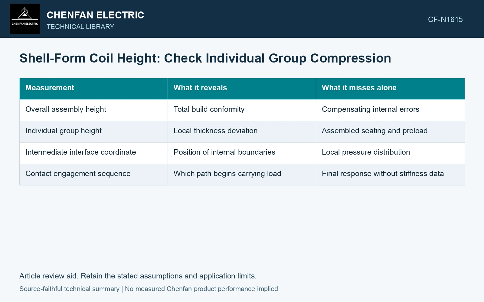
| Measurement | What it reveals | What it misses alone |
|---|---|---|
| Overall assembly height | Total build conformity | Compensating internal errors |
| Individual group height | Local thickness deviation | Assembled seating and preload |
| Intermediate interface coordinate | Position of internal boundaries | Local pressure distribution |
| Contact engagement sequence | Which path begins carrying load | Final response without stiffness data |
Identify the first contact
For parallel support paths, initial gaps and heights determine which path engages first. A high support can carry load while a neighboring path remains open. Further compression may bring the other path into contact, changing the load distribution.
Use the actual group and support geometry to establish those gaps. A nominal drawing in which every contact closes simultaneously is not a reliable model when tolerance variation is material.
Measure or model the pressure–displacement behavior under an approved procedure. Include loading history where seating is irreversible. Equal final displacement does not imply equal force when path stiffnesses differ.
Allocate tolerances to the local function
Identify which internal interfaces affect preload, insulation position and cooling passages. Control their coordinates or relationships where necessary, rather than tightening total height and hoping it governs all of them.
Keep correlated dimensions in the tolerance analysis. Groups made from the same material batch or processed together may not vary independently. A worst-case sum and a statistical estimate answer different questions and require their own assumptions.
If local compression is uneven, locate the responsible height, gap or stiffness difference before increasing clamp force. More total force may overload the first-contact path. A group-wise record shows where the assembly departs from its intended load-sharing state, even when its outer height remains correct.
Compare the hidden interface shift with a local allowance
Assume the stated +0.4/−0.4/0.0 mm group deviations are measured under the same assembly preload. Their sum is 0.0 mm, but the first interface moves +0.4 mm. With an assumed ±0.25 mm allowance at a lead-support datum, that interface is 0.15 mm outside the local allowance while total height passes. A second assumed path stiffness of 20 kN/mm converts 0.4 mm extra compression into 8 kN of additional load only while that contact remains engaged and linear. Reject total-height conformity as the sole criterion and inspect the local datum and contact history [1]. Record rated quantities and test conditions on the general power-transformer basis of IEC 60076-1 [2]. Assess the relevant measured quantities with a defined measurement model and propagated uncertainty [1].
References
- JCGM, JCGM 100:2008, Evaluation of measurement data — Guide to the expression of uncertainty in measurement, 2008.
- IEC, IEC 60076-1:2011, Power transformers – Part 1: General.