

A lead crossing a shell-form window has an electrical connection, a physical route and a magnetic relationship to nearby flux. Its insulation must be assessed against the winding groups and steel it passes. Any conductive loop formed by its supports must be assessed separately.
Start with a three-dimensional route, including bends, joints and supports. A schematic line identifies connectivity but does not show the enclosed area or local clearances.
Identify every closed conductive route
Faraday’s law relates loop voltage to flux linkage: e = −dΨ/dt, with linkage Ψ in webers for a single-turn loop and voltage e in volts. Whether a support loop experiences significant linkage depends on its actual route through the field.
Trace metallic brackets, fasteners and structural contacts. A support that appears as two separate pieces on one drawing may become a closed loop through the tank or another member. Conversely, a deliberate electrical interruption must remain effective in the assembled condition.
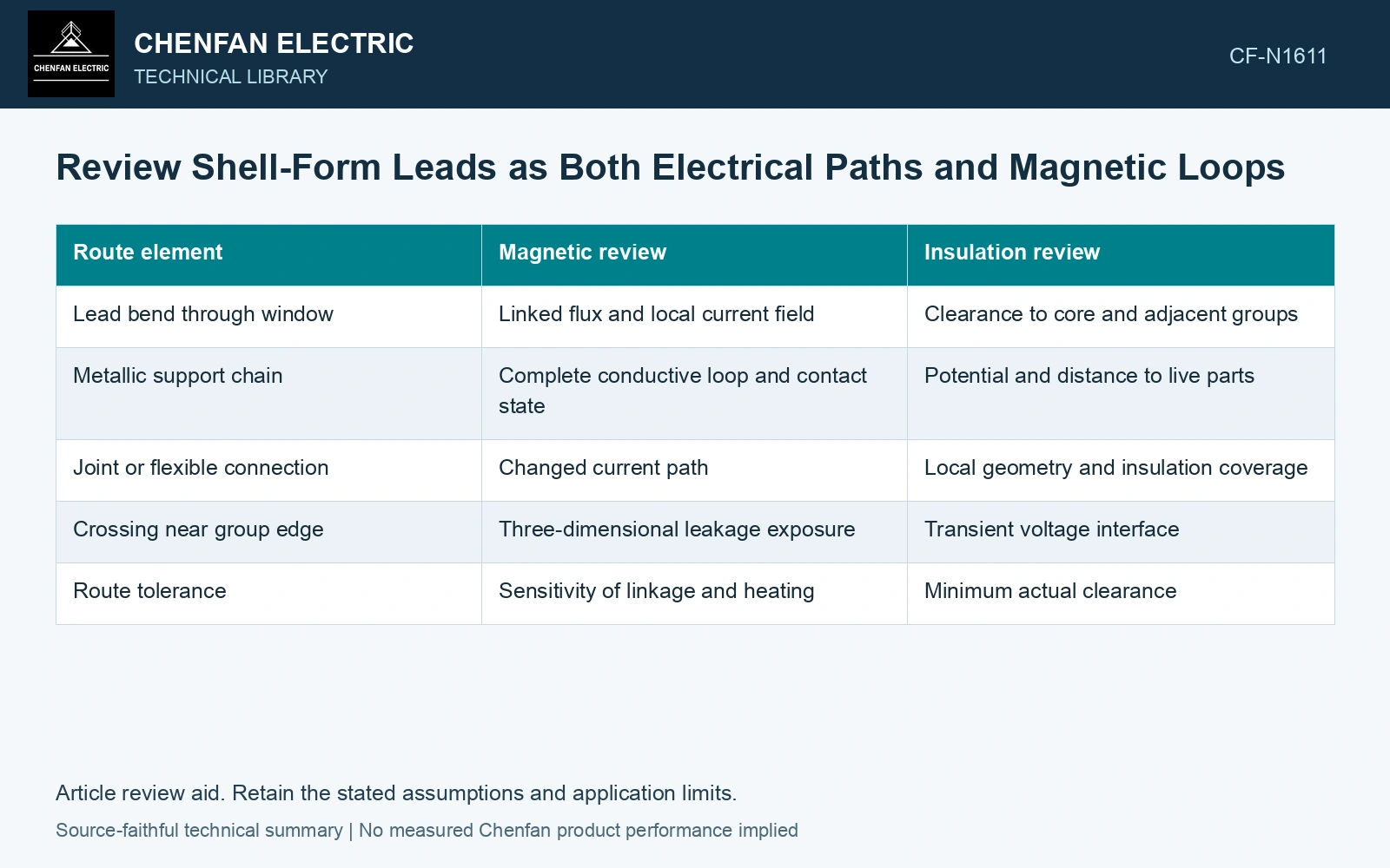
| Route element | Magnetic review | Insulation review |
|---|---|---|
| Lead bend through window | Linked flux and local current field | Clearance to core and adjacent groups |
| Metallic support chain | Complete conductive loop and contact state | Potential and distance to live parts |
| Joint or flexible connection | Changed current path | Local geometry and insulation coverage |
| Crossing near group edge | Three-dimensional leakage exposure | Transient voltage interface |
| Route tolerance | Sensitivity of linkage and heating | Minimum actual clearance |
Keep the two clearance relationships distinct
Distance from a lead to grounded steel and distance from that lead to another winding group can have different voltage duties. A single nearest-distance value is insufficient. Record the relevant potentials and transient conditions for each interface.
Include lead movement permitted by supports and manufacturing variation. The nominal route should not be the only geometry evaluated when a bend can move toward a coil corner or a core edge.
Do not infer heating from loop area alone. The linked flux waveform, loop resistance and inductive response determine current, while thermal paths determine temperature. Use the actual field and conductive path to quantify the issue where it matters.
Check the assembled route
Verify support interruptions, contact locations and clearances after the relevant assembly stage. A routing change made for accessibility can alter both magnetic linkage and insulation geometry. Record it before relying on an earlier analysis. Assess the relevant measured quantities with a defined measurement model and propagated uncertainty [1].
If an unintended loop is found, assess an approved route or support redesign. Breaking a structural connection without reviewing its mechanical and electrical function is not a complete correction.
The route review should explain where current flows intentionally, where a parasitic current could circulate and which voltage interface controls each clearance. That makes the lead arrangement assessable as an actual installed path rather than a schematic connection with one spacing annotation.
Estimate the circulating-current consequence of a support loop
Assume a single-turn metallic support loop links 0.50 mWb peak sinusoidal flux at 50 Hz. Its induced voltage is 2πfΨ/√2 = 0.1111 V RMS. With assumed resistance 1.0 mΩ and inductance 5.0 μH at an assumed temperature of 20 °C, |Z| = 1.862 mΩ, current is 59.65 A RMS and I²R loss is 3.56 W. A resistance-only estimate would predict 111.1 A and 12.34 W. Preserve the actual contact and inductive paths in the model; loop area alone cannot select the heating result or an approved support modification. Record rated quantities and test conditions on the general power-transformer basis of IEC 60076-1 [2].
References
- JCGM, JCGM 100:2008, Evaluation of measurement data — Guide to the expression of uncertainty in measurement, 2008.
- IEC, IEC 60076-1:2011, Power transformers – Part 1: General.