

When a gauge passes at one height and jams at another, repeating the diameter measurement at the passing section adds little. The failure is somewhere along the travel. Its cause may be a wider section, a displaced section center, or a local sheet projection.
Measure several sections in one coordinate system. Record their heights from a repeatable reference, fit a local center using the specified method, and separately retain the furthest surface point. The center describes the limb’s path. The outer points describe what the winding must clear.
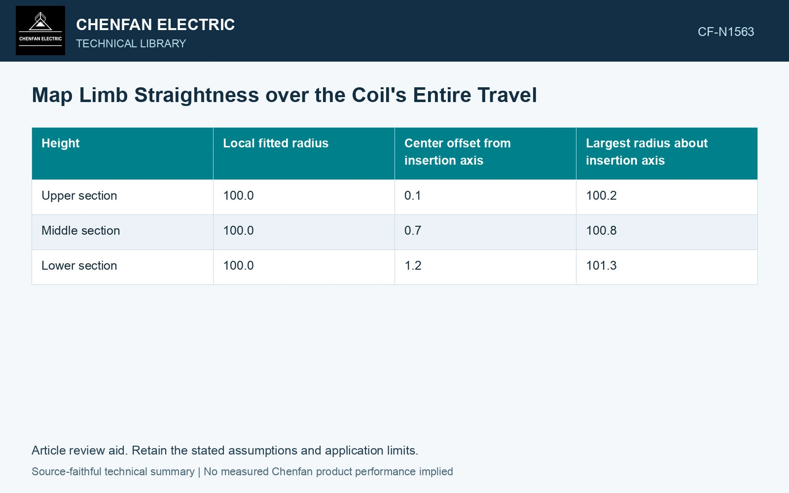
A useful height record
Assumptions for this geometric example: all table values are in millimetres. The insertion axis is fixed at x = 0, y = 0. A circular bore has a radius of 101.0 mm.
| Height | Local fitted radius | Center offset from insertion axis | Largest radius about insertion axis |
|---|---|---|---|
| Upper section | 100.0 | 0.1 | 100.2 |
| Middle section | 100.0 | 0.7 | 100.8 |
| Lower section | 100.0 | 1.2 | 101.3 |
The fitted section size barely changes. The lower section nevertheless extends beyond the bore. Its center offset is the dominant clue. The final column also includes measured surface irregularity, so it need not equal the fitted radius plus center offset exactly.
At each height, preserve both x and y center coordinates. An offset magnitude alone hides direction: a limb that moves first east and then west behaves differently from one that slopes steadily east. Connecting the centers produces a path that can be compared with the fixture axis.
Interpret the shape before correcting it
If fitted radius increases while the center stays stable, investigate section build or local compression. If centers move steadily with nearly constant radius, investigate overall tilt relative to the datum. If the center path bends, inspect support conditions and stack alignment. A single high-radius point with stable nearby points suggests a local projection rather than general limb bending.
These are diagnostic patterns, not automatic defect classifications. A distorted datum face can make a straight limb appear tilted. A measurement support can bend an assembly that will be straight in its service pose. Repeat the map after confirming the reference and support condition.
The sampling interval also matters. A large spacing between sections can miss a narrow projection. Add measurements around the actual jam height and around packet transitions. Document the regions that the instrument cannot see; interpolation through an occluded joint is not evidence of clearance.
For a rigid circular bore constrained to a straight axis, test the entire radial envelope against that axis. If the winding is allowed to translate or tilt during assembly, evaluate that specified motion instead. Do not assume that an operator can compensate for a bent centerline without checking insulation, adjacent limbs and fixture restrictions.
The map should name the limiting height and angular position. That result directs a physical correction. A single straightness number may be convenient for a report, but it cannot tell an assembler where the coil is meeting the core.
Resolve one-sheet movement along the insertion path
Catalogue nominal thickness 0.23 mm [1] supplies the scale for an assumed normal displacement of one layer. For a fixed-axis comparison, assume a section radius of 100.00 mm, a 0.60 mm center offset, one outward 0.23 mm projection, a 101.00 mm bore radius and a required 0.20 mm radial assembly allowance. Required radius becomes 100.00 + 0.60 + 0.23 = 100.83 mm; residual allowance is only 0.17 mm, below the assumed requirement. Without the projection, allowance would be 0.40 mm. Confirm the limiting height and raw peak with uncertainty [2], rather than averaging it into the fitted center path.
Manufacturing controls. Packet build, layer protrusion, support-induced bow and datum alignment control the swept envelope. Keep section centers and the furthest retained points separately; a corrected diameter at one height cannot resolve a tilted or curved limb.
References
- Nippon Steel Corporation, Grain-Oriented Electrical Steel Sheets, catalogue D004je_03_202004, 2020, Specifications; Size and Form Tolerances.
- JCGM, JCGM 100:2008, Evaluation of measurement data — Guide to the expression of uncertainty in measurement, 2008.