

An exposed steel edge and a coated lamination face can appear at different temperatures in the same infrared image even when their physical temperatures are similar. Their emissivities and reflected-radiation contributions may differ. A bright edge deserves a radiometric check before it is classified as local electrical heating.
For an opaque surface, lower emissivity increases the reflected contribution; NIST distinguishes this radiometric response from physical surface temperature [1]. The useful core-specific question is where the observed anomaly follows surface condition and where it follows an independently verified heat source.
Record the surface transition
Map coated faces, exposed edges, damaged coating, contamination and nearby reflective surfaces. Retain the camera position and viewing angle. Do not apply one assumed emissivity value to every region and then interpret the resulting contrast as a temperature difference.
Identify warm objects that can appear as reflections, including personnel, lighting or nearby equipment. Their contribution can change when the viewing position changes even if the core’s temperature does not.
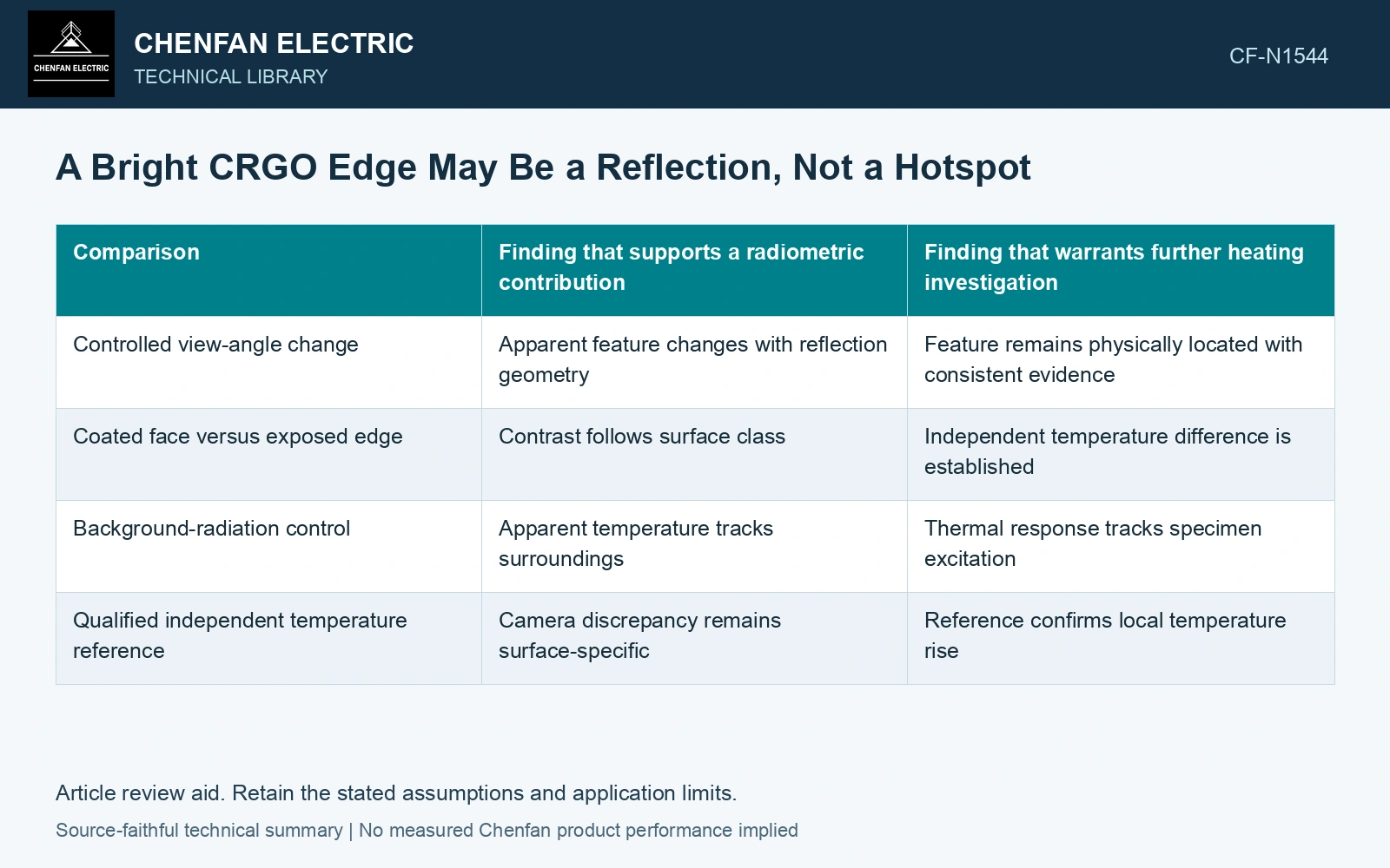
| Comparison | Finding that supports a radiometric contribution | Finding that warrants further heating investigation |
|---|---|---|
| Controlled view-angle change | Apparent feature changes with reflection geometry | Feature remains physically located with consistent evidence |
| Coated face versus exposed edge | Contrast follows surface class | Independent temperature difference is established |
| Background-radiation control | Apparent temperature tracks surroundings | Thermal response tracks specimen excitation |
| Qualified independent temperature reference | Camera discrepancy remains surface-specific | Reference confirms local temperature rise |
No single row proves a fault absent. The comparisons narrow the explanation and identify what another measurement must resolve.
Keep the reference from changing the problem
A high-emissivity reference patch may help some radiometric measurements, but adding material to a lamination or joint can alter clearance, thermal transfer or electrical contact. Its placement and material need assessment before use. Do not cover an active joint or apply an unqualified coating merely to improve the image.
An independent contact sensor also introduces a local thermal and mechanical boundary. Record its placement and evaluate whether it significantly changes the region being measured. Use a suitable reference method for the actual geometry.
Examine the time response
Track apparent temperature before, during and after a controlled, professionally defined test condition. A thermal source and a changing reflection can have different histories, but the difference must be observed rather than assumed. Preserve the radiometric settings and raw data where the system provides them.
Check spatial resolution at thin edges. One pixel or measurement spot may average coated steel, a bare edge and background. A small bright feature can therefore be sensitive to alignment and focus.
The inspection record should distinguish an unresolved bright feature, a surface-radiation artifact and independently supported heating. This prevents a coating transition from becoming a false short-circuit diagnosis while also avoiding the opposite error of dismissing a real hotspot merely because the surface is reflective.
Calculate a mixed edge pixel before calling it hot
Nominal 23ZH90 thickness is 0.23 mm [2]. Assume that bare edge fills 23% of a 1.00 mm pixel, the rest is coated steel, both are at 300 K, reflected surroundings are at 320 K, and grey-body emissivities are 0.20 and 0.90. The mixed emissivity is 0.23 × 0.20 + 0.77 × 0.90 = 0.739. A broadband blackbody interpretation of εT⁴ + (1 − ε)Treflected⁴ gives 305.61 K for the mixed pixel and 302.19 K for coated steel alone: an apparent contrast of 3.42 K without real heating. This simplified radiance example excludes spectral camera response. Use calibrated radiometric settings and uncertainty [3] [1] before temperature attribution.
Manufacturing controls. Edge exposure, coating damage, burr orientation and packet alignment change the visible surface mixture. Control viewing geometry and surface classification without applying a repair material that changes the joint contact or clearance.
References
- Deisenroth, D. C. et al., Measurement Uncertainty of Surface Temperature Distributions for Laser Powder Bed Fusion Processes, Journal of Research of NIST 126, 126013, 2021, sections 1.5 and 2.1; DOI: 10.6028/jres.126.013.
- Nippon Steel Corporation, Grain-Oriented Electrical Steel Sheets, catalogue D004je_03_202004, 2020, Specifications; Size and Form Tolerances.
- JCGM, JCGM 100:2008, Evaluation of measurement data — Guide to the expression of uncertainty in measurement, 2008.