

An adhesive layer occupies space that steel cannot occupy. What this means for a transformer core depends on the design constraint. With a fixed number of sheets, additional nonmagnetic thickness enlarges the packet. With a fixed permitted envelope, it can reduce the number of sheets that fit. Those are different comparisons, even when the adhesive is identical.
Start with the dimensions used in the drawing and material records. A supplied sheet-thickness measurement may include coatings. Do not use that value as steel-only thickness and then add the same coating again. An explicit thickness convention prevents a small per-layer error from accumulating through the stack.
A transparent geometric calculation
For an illustrative packet of constant width w, let N be sheet count, t_s the steel-only sheet thickness, t_c the total original coating thickness per sheet, and b_i the adhesive thickness at interface i. Measure all lengths in metres. Ignoring edge variations and compression of the steel itself, stack thickness H is:
H = N(t_s + t_c) + sum of b_i, for the N−1 internal interfaces.
The net steel cross-sectional area in this simplified geometry is A_s = w N t_s, in square metres. Adhesive may affect magnetic behavior through several mechanisms, but its geometric contribution here is to H rather than A_s.
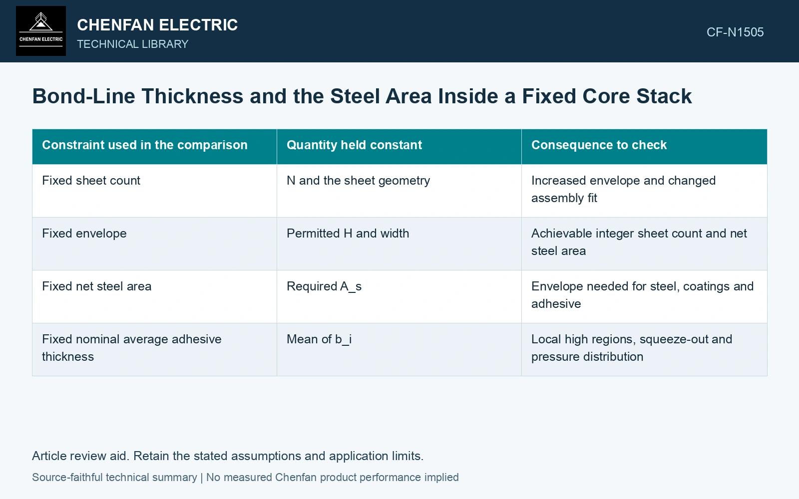
| Constraint used in the comparison | Quantity held constant | Consequence to check |
|---|---|---|
| Fixed sheet count | N and the sheet geometry | Increased envelope and changed assembly fit |
| Fixed envelope | Permitted H and width | Achievable integer sheet count and net steel area |
| Fixed net steel area | Required A_s | Envelope needed for steel, coatings and adhesive |
| Fixed nominal average adhesive thickness | Mean of b_i | Local high regions, squeeze-out and pressure distribution |
For a fixed envelope, do not treat sheet count as a continuous number. A calculated allowance may permit one less whole layer, requiring a drawing or assembly decision. The approved design determines whether that change is permissible.
The mean hides where a stack becomes thick
An average bond-line thickness can be acceptable while a local region exceeds the intended envelope. Record thickness at positions relevant to fit, joint seating and packet support. Compare the measurements under a defined pressure and after release; changing compression state changes the observed distribution.
A sectioned representative specimen can reveal individual interfaces, but its preparation may disturb soft or weak layers. Preserve the sampling location, support condition and measurement method. Optical measurements at an edge also need a check that the edge represents the interior. Adhesive flow can make the two differ.
Carry the geometry into the magnetic comparison
If a magnetic test compares packets with different steel quantities, a change in measured loss cannot be attributed solely to bonding stress. State the actual sheet count, net steel area, joint arrangement and excitation. For a uniform flux approximation, flux density depends on flux divided by net magnetic area; the approximation itself should be identified where local joint fields are important.
The thickness record should therefore contain separate columns for sheet count, original sheet-thickness convention, adhesive contribution, total envelope and assembly state. That record shows whether a proposed bonding change uses available space, changes the steel quantity, or introduces a local interference that an average thickness calculation missed.
Technical references
- voestalpine. Backlack: Lamination bonding.
- voestalpine. Backlack: Testing methods and production of test specimens.