

The visible bead at the edge of a bonded packet is easy to photograph. Adhesive inside a step-lap clearance is harder to establish, and it may be the more relevant feature. An external bead can be large without occupying the intended joint space. A smaller bead can accompany intrusion into a narrow, inaccessible location.
Treat squeeze-out as a geometry problem first. Identify the surfaces that must approach, overlap or remain clear in the assembled joint. Then locate the cured adhesive relative to those surfaces. The magnetic consequence depends on what geometry has changed; bead size alone is an incomplete acceptance measure.
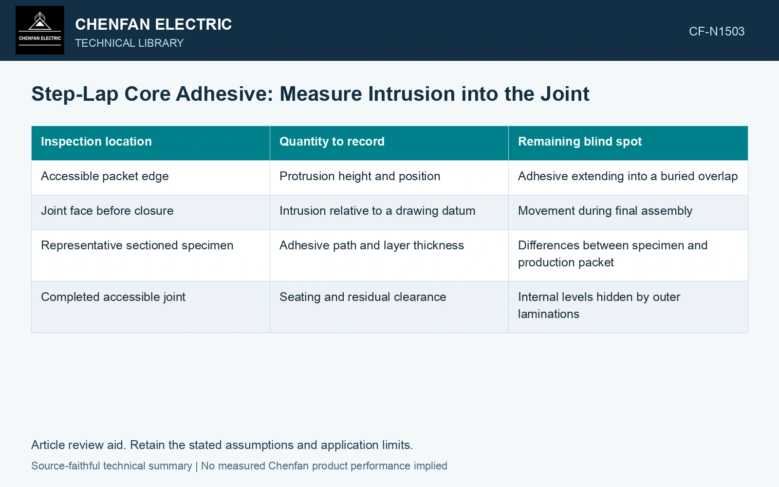
Three quantities with different meanings
Bond-line thickness describes adhesive between neighboring sheets in the bonded region. Protrusion describes material extending beyond an edge. Intrusion describes adhesive entering a protected clearance or interfering with the intended seating of joint surfaces. A measurement procedure should name which quantity it reports.
Do not infer intrusion depth from the total volume of visible adhesive. Flow during pressing can follow local pressure gradients and surface paths, and the final shape may be uneven. Where the joint contains multiple levels, inspect each relevant level or justify how the sampling represents them.
| Inspection location | Quantity to record | Remaining blind spot |
|---|---|---|
| Accessible packet edge | Protrusion height and position | Adhesive extending into a buried overlap |
| Joint face before closure | Intrusion relative to a drawing datum | Movement during final assembly |
| Representative sectioned specimen | Adhesive path and layer thickness | Differences between specimen and production packet |
| Completed accessible joint | Seating and residual clearance | Internal levels hidden by outer laminations |
This inspection map should be prepared before the assembly sequence removes access. A finished-core photograph cannot recover evidence from a surface that was never recorded.
Give the intrusion a coordinate
For an illustrative record, set the origin at the approved joint reference edge and measure distance toward the intended clearance. Record the most advanced observed adhesive position, its layer or packet identifier, and the measurement uncertainty. Use the drawing’s actual geometry; a single generic distance is not transferable between different step-lap arrangements.
An edge-profile scan can make accessible protrusions repeatable. Manufacturer work on bonded electrical-steel specimens illustrates this use of laser triangulation. It does not show that the same scan reaches an enclosed transformer joint. Access and detection capability need verification on representative geometry, including a known intrusion feature.
Investigate interference before assigning a loss penalty
If adhesive changes seating, compare the actual assembled geometry with the intended contact and clearance. Check whether the observed effect is a local displaced lamination, an altered overlap, or a region kept apart by cured material. These lead to different corrective actions and magnetic models.
A controlled trial can compare protected and deliberately varied joint conditions using the same material and excitation. It should establish the observed geometry alongside magnetic measurements, without assigning a universal loss increase to an adhesive bead. A useful disposition identifies the affected layer and surface: remove a process cause, revise access for inspection, or qualify a changed clearance. Calling the edge visually tidy leaves the buried question unanswered.
Technical references
- voestalpine. Backlack: Lamination bonding.
- voestalpine. Backlack: Testing methods and production of test specimens.