

A bonded lamination has at least three materials in its load path: steel, the original insulating coating, and adhesive. A reported breaking load cannot tell a transformer engineer which of those materials carried the load successfully. The adhesive may remain intact while the coating separates from the steel underneath it.
That distinction changes the next action. Buying a stronger adhesive will not repair a weak steel-to-coating interface. Increasing surface abrasion may improve mechanical attachment while damaging the insulation that the lamination needs. The qualification question is therefore where the joint fails, under which preparation and loading conditions.
Preserve a reference surface
Take paired specimens from an identified steel coil and coating condition. Keep rolling direction, thickness, joint area, cure history and specimen geometry consistent. Reserve untreated material before evaluating any proposed cleaning step. It provides a reference for coating appearance, surface insulation and magnetic behavior after the same handling history.
The cleaned specimen must pass two separate checks: whether the surface condition supports bonding, and whether preparation has altered the original coating. A visually clean surface does not establish either result. Solvent compatibility and abrasive preparation require their own material-specific verification; they cannot be inferred from a cleaner’s general description.
Record both fracture faces
Inspect the two separated faces as a pair. A photograph of one face may hide transferred coating or adhesive. Label the original sheet, face, joint position and loading direction before testing, so that fracture observations remain connected to the specimen rather than to an anonymous broken strip.
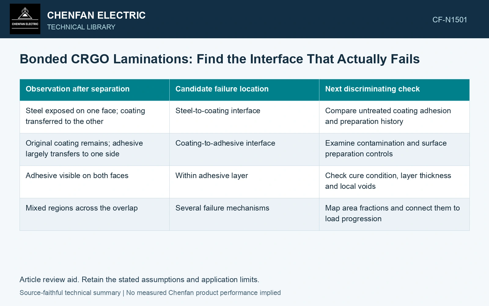
| Observation after separation | Candidate failure location | Next discriminating check |
|---|---|---|
| Steel exposed on one face; coating transferred to the other | Steel-to-coating interface | Compare untreated coating adhesion and preparation history |
| Original coating remains; adhesive largely transfers to one side | Coating-to-adhesive interface | Examine contamination and surface preparation controls |
| Adhesive visible on both faces | Within adhesive layer | Check cure condition, layer thickness and local voids |
| Mixed regions across the overlap | Several failure mechanisms | Map area fractions and connect them to load progression |
These are hypotheses for investigation. Thin residues can be difficult to identify by eye, and a torn coating may expose several layers. Microscopy or suitable surface analysis should resolve ambiguous areas before assigning a mechanism.
Keep the electrical consequence in the same trial
Mechanical failure location and insulation performance belong in the same record. Measure the appropriate surface or interlaminar electrical response before preparation, after preparation, and after the relevant conditioning. Use comparable contact geometry and pressure. Otherwise a change in the test fixture can look like coating damage.
A useful record contains the material identity, preparation, actual thermal history, bond-line condition, breaking-load trace, fracture map and electrical observations. It also states which observations remain unresolved. This lets an engineer distinguish a bond that is weak, a coating that is weakened by preparation, and a joint that merely failed outside its intended loading mode.
Motor-lamination bonding literature offers useful specimen and process concepts. It does not establish the same interface behavior in CRGO or an oil-immersed transformer. The first production decision should be to retain, revise or reject the tested material combination, based on its identified failure path.
Technical references
- voestalpine. Backlack: Lamination bonding.
- voestalpine. Backlack: Testing methods and production of test specimens.