

Two transformer core packets can contain the same quantity of adhesive and behave differently. A continuous bonded strip near an edge can block layer movement across that edge. Several separated spots may leave paths for local slip between them. Total bonded area alone does not describe that difference.
Define the motion that the bond is intended to control before choosing a pattern. Is the concern handling displacement, packet bending, edge separation, or alignment at a particular joint? A layout designed for one of these movements may introduce restraint where another movement should remain possible.
Start with a restraint map
Draw the contact face and mark the areas intended to remain unbonded. Include joints, cooling passages, inspection access and any assembly operation requiring later movement. Then draw the expected displacement under the chosen mechanical load. This connects adhesive placement to a physical purpose instead of making coverage percentage the design objective.
For a flat, known contact face, nominal bonded fraction is bonded projected area divided by available face area. State how excluded passages and edge clearances enter the denominator. The cured effective area may be smaller than the applied area because of voids or incomplete contact; it must be checked separately.
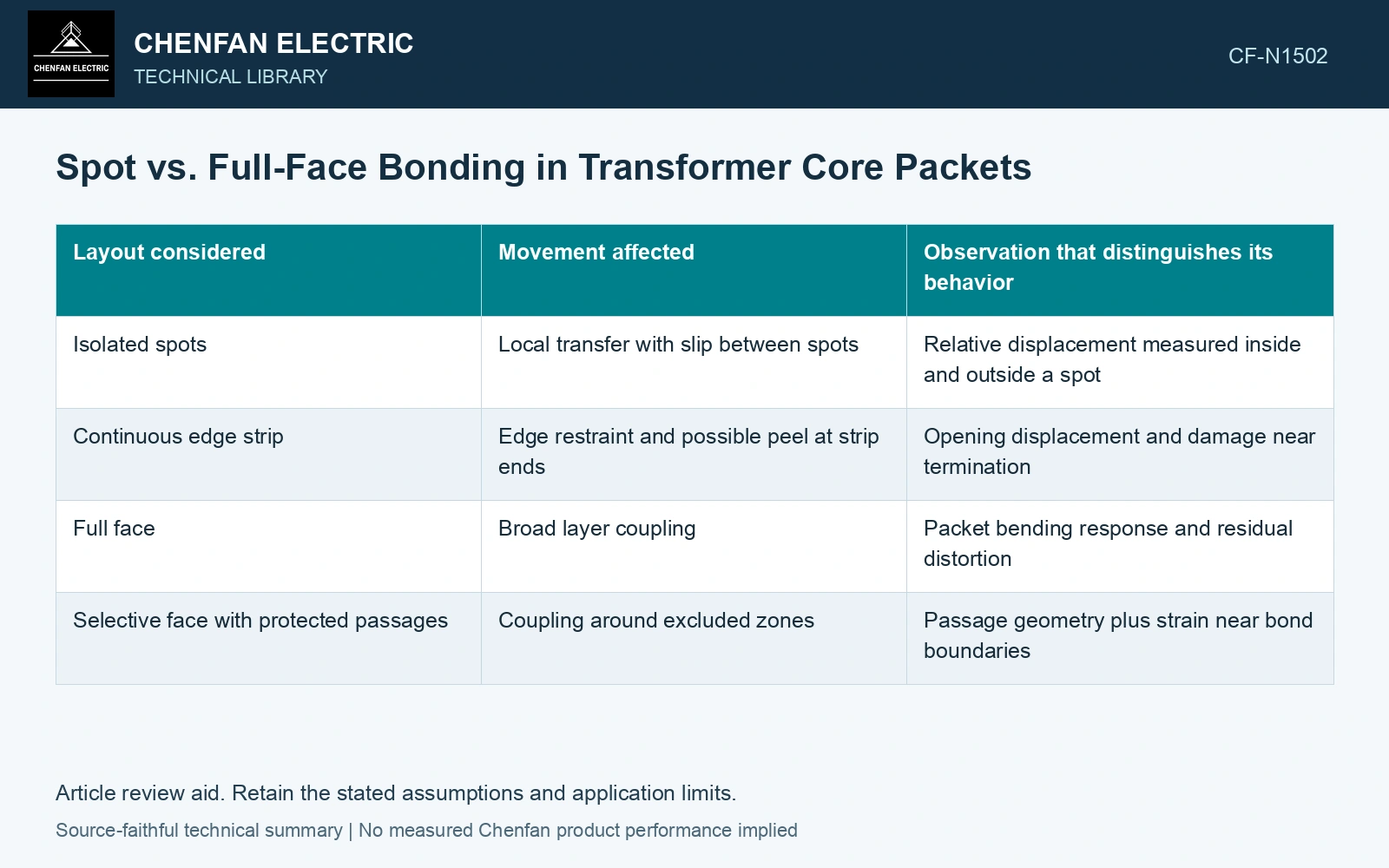
| Layout considered | Movement affected | Observation that distinguishes its behavior |
|---|---|---|
| Isolated spots | Local transfer with slip between spots | Relative displacement measured inside and outside a spot |
| Continuous edge strip | Edge restraint and possible peel at strip ends | Opening displacement and damage near termination |
| Full face | Broad layer coupling | Packet bending response and residual distortion |
| Selective face with protected passages | Coupling around excluded zones | Passage geometry plus strain near bond boundaries |
The table describes candidate mechanisms. It does not rank the layouts. Spot size, spacing, adhesive condition and packet geometry can reverse a comparison based only on the names of the processes.
Compare a pattern with its actual alternative
Use identified, matched steel and equivalent cutting and stacking histories. If spot bonding is being compared with face bonding, hold the intended assembly geometry and mechanical boundary conditions constant. Measure initial shape, movement under load, and shape after unloading. A packet that looks stiff while the fixture holds it may distort when released.
Map slip or opening where the predicted load transfer changes. Measuring only the largest external displacement can miss concentration around a spot or at the end of a bonded strip. Conversely, measuring only the adhesive region can miss movement that the unbonded area permits.
A mechanical improvement needs its magnetic cost
Bonding may change contact, residual stress, joint geometry or the amount of steel within a fixed stack envelope. A mechanical result therefore needs paired magnetic evaluation under the same stated excitation and assembly condition. Keep the observed changes separate: a smaller handling displacement is one result; a change in loss or excitation current is another.
Specify the acceptable combination for the intended product rather than collapsing both into a single promotional score. If one pattern passes the mechanical requirement but alters magnetic behavior beyond the permitted design allowance, increasing its coverage is unlikely to answer the original question. The restraint map shows where a revised pattern should be tested next.
Technical references
- voestalpine. Backlack: Lamination bonding.
- voestalpine. Backlack: Testing methods and production of test specimens.