

Short answer
Harmonic filter tolerance drift moves the tuning frequency because it depends on the product of inductance and capacitance: the tuned order is proportional to one over the square root of LC. Manufacturing tolerances, temperature, ageing and failed capacitor elements all change C and L. In an illustrative filter tuned to the 4.7th harmonic, capacitance falling 5 % and inductance rising 2 % move tuning to about 4.78; capacitance rising 3 % moves it to about 4.63. Capacitor element failures typically lower capacitance over time, pushing tuning upward toward the 5th, where the filter would absorb much more current than designed and could be overloaded. The parallel resonance with the system, just below the tuning point, moves as well. Designs therefore tune slightly below the target harmonic with margin for expected drift.
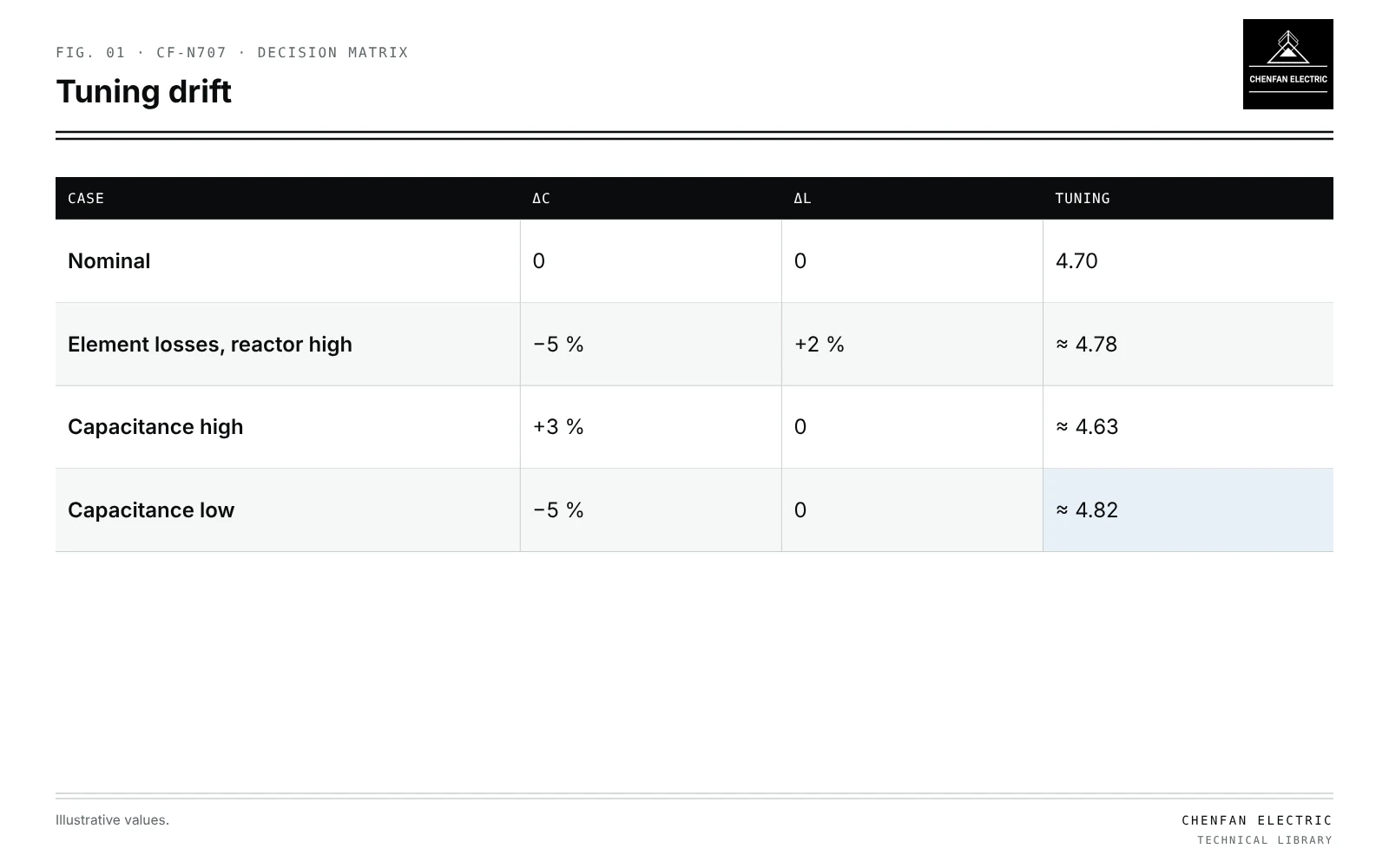
Tuning sensitivity
| Case | ΔC | ΔL | Tuning |
|---|---|---|---|
| Nominal | 0 | 0 | 4.70 |
| Element losses, reactor high | −5 % | +2 % | ≈ 4.78 |
| Capacitance high | +3 % | 0 | ≈ 4.63 |
| Capacitance low | −5 % | 0 | ≈ 4.82 |
h_t = 1 / (ω_1 sqrt(L C))
Δh_t / h_t ≈ −(ΔL / L + ΔC / C) / 2
A total change of −3.1 % in LC moves tuning up by about 1.6 %.
Illustrative cases
Illustrative example. Filter designed at 4.7th harmonic. Values chosen for demonstration.
| Case | ΔC | ΔL | New tuning |
|---|---|---|---|
| Nominal | 0 | 0 | 4.70 |
| Element losses, reactor high | −5 % | +2 % | ≈ 4.78 |
| Capacitance high | +3 % | 0 | ≈ 4.63 |
| Capacitance low only | −5 % | 0 | ≈ 4.82 |
At 4.82, the filter is closer to the 5th and its impedance there falls, so it absorbs more 5th harmonic current from the whole network, not only from local loads.
Sources of drift
- Manufacturing tolerance of capacitors and reactors.
- Temperature: capacitor dielectric and reactor dimensions change.
- Element failures in internally fused capacitors reduce capacitance stepwise; see capacitor unbalance protection with internally fused units.
- Unit loss in externally fused banks; see external-fuse capacitor banks.
- Reactor tap settings where adjustable.
Effects
- Absorbed current rises sharply as tuning approaches the target harmonic.
- Parallel resonance between filter and system, below tuning, may approach a lower harmonic present in the network.
- Quality factor determines how sharply current changes with drift; see single-tuned and damped filters on transformer buses.
Design margins
- Tune below the target harmonic, for example around 4.7 for the 5th, accounting for capacitance loss over life.
- Rate components for the current at the worst-case tuning.
- Monitor filter current and capacitance; trend changes.
- Retune using reactor taps if drift exceeds limits.
Resonance scans at varied component values are covered in resonance scans with frequency-dependent transformer damping.
What this article does not cover
The list of spectrum inputs for specifying filter reactors is not repeated here.
Where this reasoning stops. The sensitivity formula is a first-order approximation; large changes need direct calculation.
Practical takeaway
Calculate tuning across combined tolerance, temperature and element-loss cases, tune below the target harmonic with margin, rate components at worst-case tuning, and trend capacitance in service.
Reference framework
- IEC 61642, Industrial a.c. networks affected by harmonics: application of filters and shunt capacitors.
- IEEE 1531, Guide for the application and specification of harmonic filters.